External connections, 3 external connections – Comtech EF Data SMS-458B User Manual
Page 30
SMS-458B Modem Protection Switch
Revision 2
Installation
MN/SMS458B.IOM
2–4
2.3 External
Connections
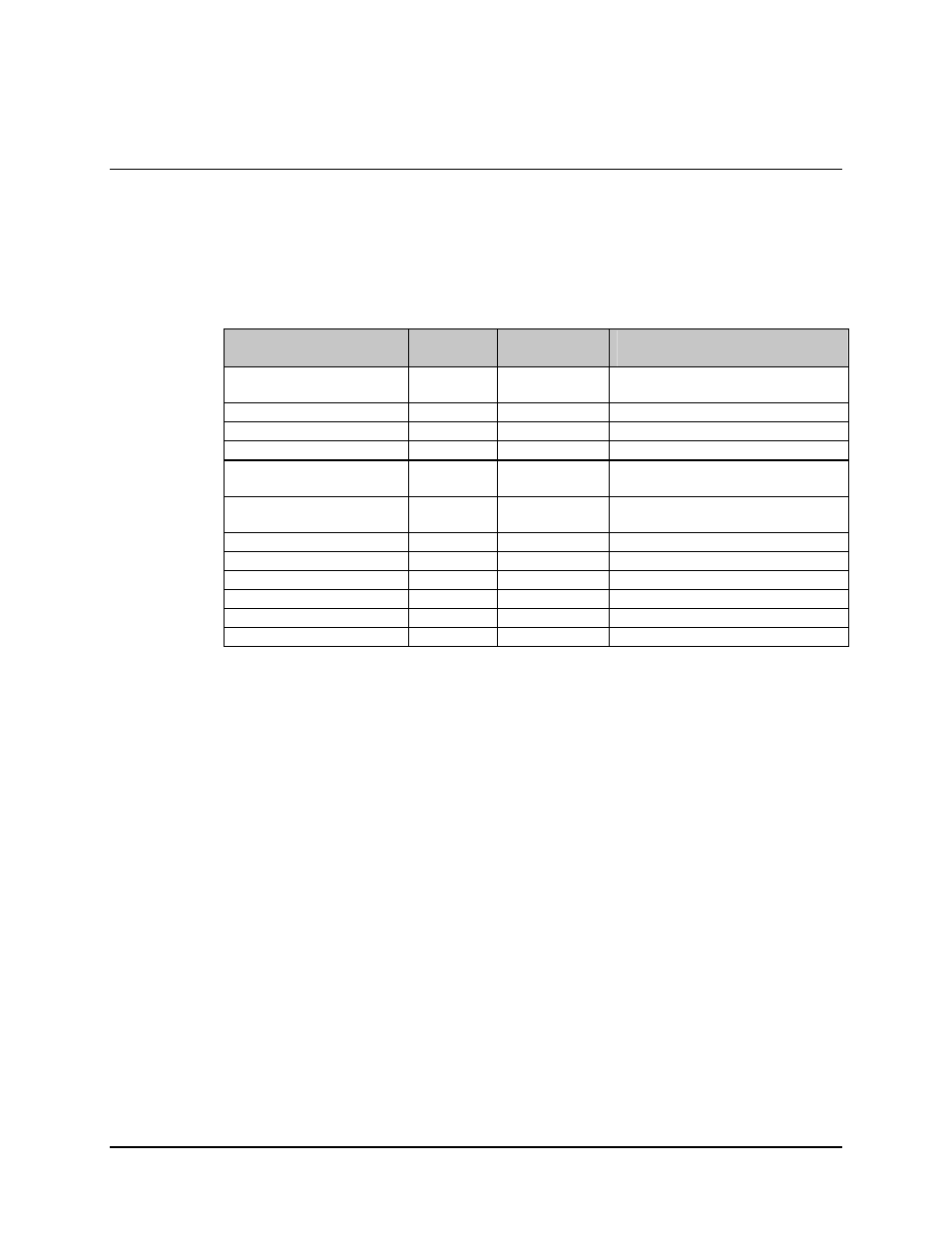
All connections between the switch and other equipment are made through rear panel
connections. Table 2-1 lists these connectors, and Figure 2-2 shows their locations. The
uses of these connectors are described in the following sections.
Table 2-1. Rear Panel Connections
Name
Ref Desig
Connector
Type
Function
DATA I/O MODULES
J5, J6
J1 – J4
50-pin D BNC
BNC
Mod, Demod Faults
G.703, ECL/HSSI, I/O
REMOTE
J1, J2, J3
9-pin D
Remote Interface
ON-LINE STATUS
J4, J5
25-pin D
Online Status Reporting
RELAY/REMOTE FAULTS
J6
25-pin D
Relay/Remote and Faults
DOWNLINK INPUTS
J7 to J10,
J12 to J15
BNC
Downlink IF Inputs
BACK-UP DEMODS
J11, J16
BNC
Downlink Outputs to Backup
Demods
PRIME MOD INPUTS
J18 to J25
BNC
Modulator IF Inputs
BACK-UP MOD INPUTS
J26, J36
BNC
Backup Mod IF Inputs
OFF-LINE IF OUTPUTS
J17, J27
BNC
Offline Mod IF Outputs
IF OUTPUTS
J28 to J35
BNC
IF Outputs to Uplinks
AC POWER
J37, J38
CEE22
AC Power Input
GROUND
J39
#10-32 stud
Chassis Ground
Note: All unused BNC connectors must have a 75
Ω termination.