System and modem setup, Prime uplink and downlink ports, System setup – Comtech EF Data SMS-458B User Manual
Page 43: 2 system setup
SMS-458B Modem Protection Switch
Revision 2
Operation
MN/SMS458B.IOM
3–7
3.4
System and Modem Setup
3.4.1
Prime Uplink and Downlink Ports
J28 through J35
Eight IF outputs available to connect to customer-supplied uplink power
combiners.
Note: Only J28 through J31 are used for this switch.
J7, J8, J9, J10
J7 through J10 are used when four downlink transponders are specified in the
system.
The following steps describe the uplink and downlink connections:
1. Connect the IF output cables 1 to 4 to the appropriate customer-furnished uplink
signal combiner inputs.
2. Connect the Downlink input cables 1 to 4 to the appropriate customer-furnished
downlink splitters.
Note: Be sure to terminate all unused IF outputs and downlink inputs with one of the
supplied 75
Ω BNC terminations.
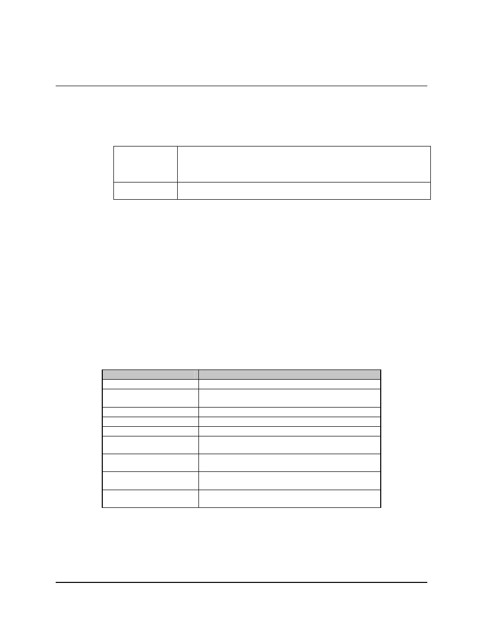
3.4.2 System
Setup
Enter the SYSTEM SETUP menu to enter, change, or view the system setup
configuration. The definitions of the system setup functions are as follows:
Function
Description
TIME AND DATE
Time and date are entered and displayed.
DOWNLINK OPTIONS
Prime and backup downlinks are selected and
displayed.
PRIME MODS
Active prime modulators are selected and displayed.
PRIME DEMODS
Active prime demodulators are selected and displayed.
BACKUP MODS
Active backup modulators are selected and displayed.
BACKUP DEMODS
Active backup demodulators are selected and
displayed.
MODEM ADDRESSES
Prime and backup modem addresses are selected and
displayed.
*PRIME C/U
Active prime channel unit addresses are selected and
displayed.
*BACKUP C/U
Active backup channel unit addresses are selected and
displayed.
* Note: These functions are applicable only for Version 2.02.