Comtech EF Data CRS-180 User Manual
Page 91
CRS-180 70/140 MHz IF 1:1 Redundancy Switch
MN/CRS180.IOM
Cables and Connections
Revision 11
5–31
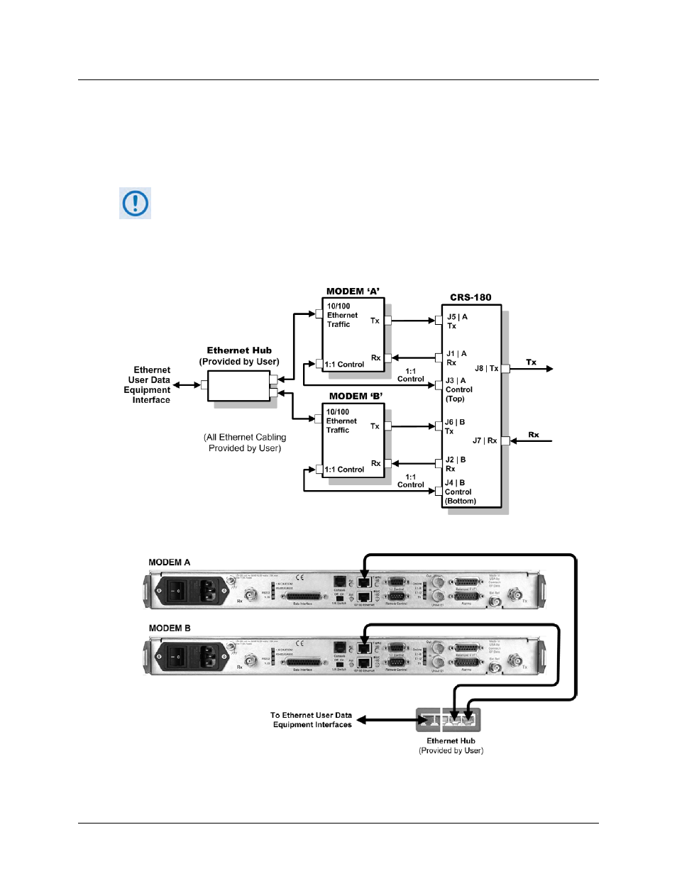
5.4.2.2 Modem-to-User IP (10/100 Ethernet) Interface Example
Figure 5-28 shows the block diagram and cabling example of a CDM-570/A 1:1 modem
configuration using the optional IP (10/100 Ethernet) Module (CDM-570) or Packet Processor
(CDM-570A) interface. This configuration requires no cabling kit – you must use user-provided
Ethernet cables and hub for direct connection to the ports.
For the CDM-570/A in Managed Switch (Ethernet Bridge) Mode, you MUST use an
external Ethernet hub to ensure that traffic will continue after a switchover. If an
Ethernet switch is used, there could be a several minute outage while the Ethernet
Switch “re-learns” the correct output Ethernet port. Using a “dumb” Ethernet hub
allows LAN to WAN traffic to continue even after a switchover occurs since both
modems will be receiving the LAN traffic.
CDM-570/A Block Diagram – 10/100 Ethernet Interface in Managed Switch Mode
Figure 5-28. CDM-570/A 10/100 Ethernet 1:1 Example – Managed Switch Mode