2 physical features, 1 modem side features, 2 physical features 1.2.1 modem side features – Comtech EF Data CRS-180 User Manual
Page 22
CRS-180 70/140 MHz IF 1:1 Redundancy Switch
MN/CRS180.IOM
Introduction
Revision 11
1–2
Table 1-1. CRS-180 Compatibility Summary
Modem
1:1 Data Switch
Firmware/Hardware Requirement*
CDM-625/A
Built into the CDM-625/A
Firmware Ver. 1.1.1 or higher
CDM-760
Built into the CDM-760
Firmware Ver. 1.1.1 or higher
CDM-750
Built into the CDM-750
Firmware Ver. 1.1.1 or higher
CDM-570A
Built into the CDM-570A
Firmware Ver. 1.1.1 or higher
CDM-570A with Optional IP Packet
Processor
User-provided Layer 2 switch or hub Firmware Ver. 1.2.1 or higher
CDM-570
Built into the CDM-570
•
Firmware Ver. 1.6.7 or higher
•
Hardware Revision 3
CDM-570 with Optional IP Module
User-provided Layer 2 switch or hub Firmware Ver. 1.5.4.2 or higher
CDM-710G
Built into the CDM-710G
Firmware Ver. 5.1.1 or higher
CDM-710
Built into the CDM-710
•
Firmware Ver. 2.4.1 or higher
•
Hardware Revision 3
CDM-700
Built into the CDM-700
•
Firmware Ver. 1.1.6 or higher
•
Hardware Revision 3
* Firmware updates are free and may be downloaded from the Comtech EF Data web site
(http://www.comtechefdata.com). If a modem does not meet the hardware requirements,
contact Comtech EF Data Product Support. Hardware revision upgrades must be performed
at CEFD.
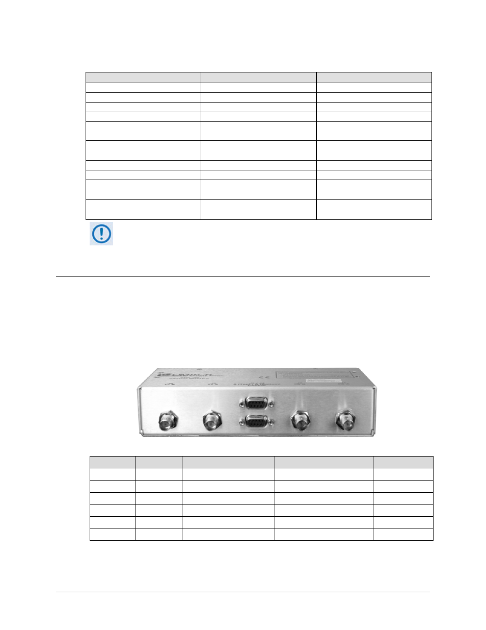
1.2 Physical Features
1.2.1 Modem Side Features
Figure 1-2 shows the modem side of the CRS-180. The connectors provided here facilitate all
necessary external connections between the CRS-180 and the compatible Comtech EF Data
modems.
J6 Tx B
J5 Tx A
J3 Control A
J4 Control B
J2 Rx B
J1 Rx A
Ref Des
Name
Connector Type
Function
Chapter Sect.
J1
Rx A
BNC
IF Input to Modem ‘A’
3.2.1.1
J2
Rx B
BNC
IF Input to Modem ‘B’
3.2.1.1
J3
Control A
DB-9F 9-pin Type ‘D’ female Modem ‘A’ Control Interface
3.2.1.2
J4
Control B
DB-9F 9-pin Type ‘D’ female Modem ‘B’ Control Interface
3.2.1.3
J5
Tx A
BNC
IF Output from Modem ‘A’
3.2.1.1
J6
Tx B
BNC
IF Output from Modem ‘B’
3.2.1.1
Figure 1-2. CRS-180 – Modem Side Features