6 configure switch dip settings – Comtech EF Data CRS-180 User Manual
Page 59
CRS-180 70/140 MHz IF 1:1 Redundancy Switch
MN/CRS180.IOM
Modem and Switch Configuration
Revision 11
4–17
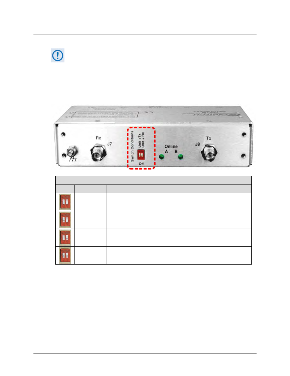
4.6 Configure Switch DIP Settings
The “Switch Conditions” DIP switches are set depending upon the type of Tx or Rx
traffic conditions that are resultant of switchover. Some modems have additional
settings or alarm masks that affect conditions – see your pertinent modem
Installation and Operation Manual for detailed explanations.
Figure 4-3 shows the DIP switches located on the antenna side of the CRS-180. The table
provided here shows the settings that determine “Switch Conditions” – the switchover
functionality for a given redundancy configuration.
“Switch Conditions” DIP Settings
DIP
Left Switch
Right Switch Result
Down (Off)
Down
Switchover upon a Unit fault
Up
Down
Switchover upon a Unit or Tx Traffic fault
Down
Up
Switchover upon a Unit or Rx Traffic fault
Up
Up
Switchover upon a Unit or Tx Traffic or Rx Traffic fault
Figure 4-3. CRS-180 “Switch Conditions” DIP Switches