Comtech EF Data CRS-180 User Manual
Page 26
CRS-180 70/140 MHz IF 1:1 Redundancy Switch
MN/CRS180.IOM
Introduction
Revision 11
1–6
Any new arriving packets destined for that MAC address will be forwarded only out the port
identified in the CAM table. Most switch CAM tables do have a flush or timeout value, but is
normally set to a very high number to limit the amount of times the switch has to broadcast a
packet out all ports. It is also important to note that CAM entries for a specific port are cleared
when a port link goes down.
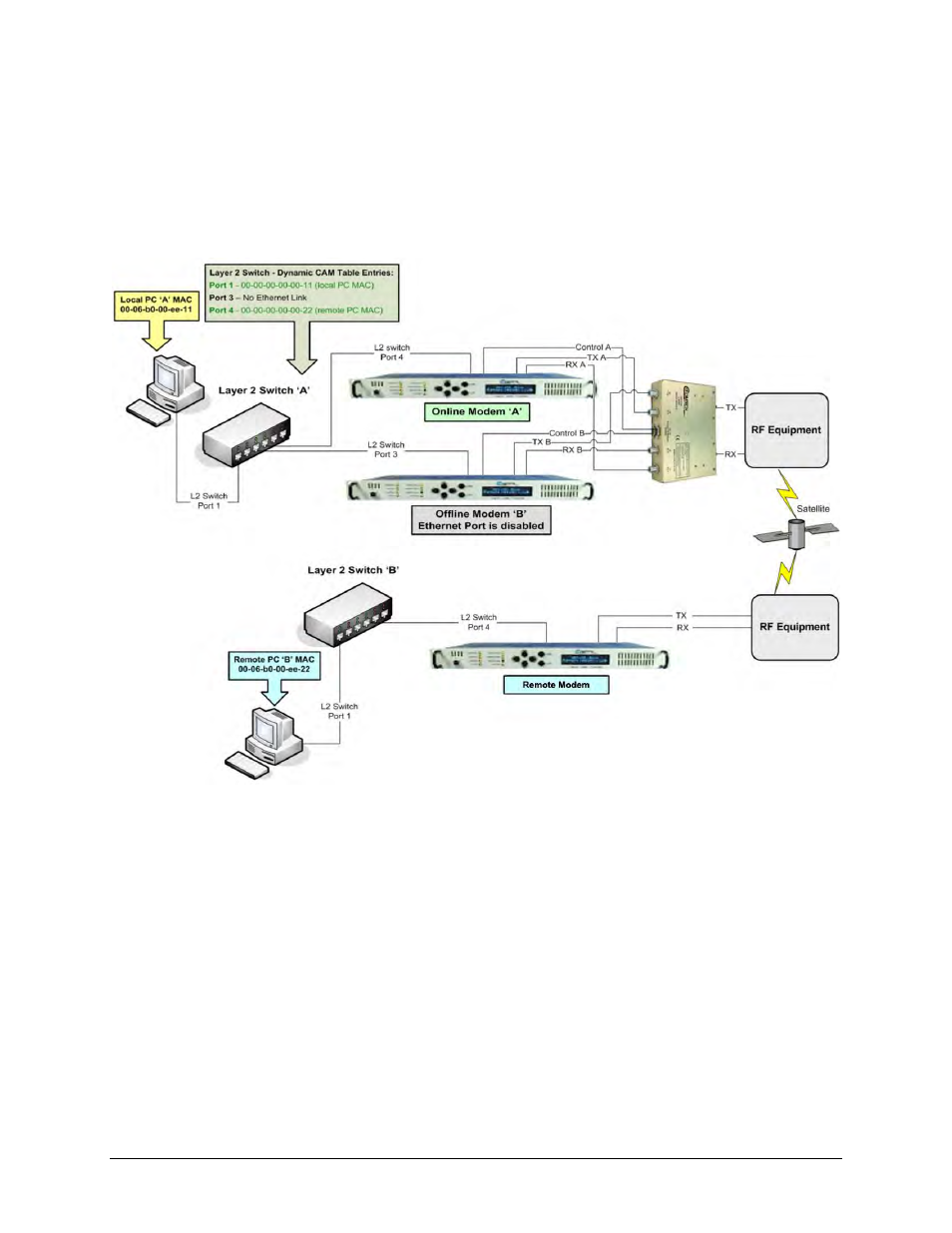
Figure 1-4. CDM-625/A, -760, -750, -710G, -710, -700 1:1 IP Redundancy Managed
Switch Mode
Figure 1-4 shows a Managed Switch Mode 1:1 IP Redundancy setup with the Ethernet data interface
of both modems connected to a Layer 2 switch. Both modems are operational – Modem ‘A’ is Online
and connected to Port 4 of the Layer 2 switch. Modem ‘B’ is Offline and connected to Port 3 of the
Layer 2 switch, but the Ethernet link is not active because only the Online modem will have an active
Ethernet data interface. Also, Local PC ‘A’ is connected to Port 1 of the Layer 2 switch.
When Ethernet traffic is sent from Local PC ‘A’ across the satellite link to remote PC ‘B’, the
Layer 2 switch will “learn” the MAC addresses of both PCs and will have these dynamic entries in
its CAM Table:
Port 1 MAC 00-00-00-00-00-11 (Local PC ‘A’)
Port 3 No entries, port down
Port 4 MAC 00-00-00-00-00-22 (Remote PC ‘B’)