3 quad e1 interface example – Comtech EF Data CRS-180 User Manual
Page 68
CRS-180 70/140 MHz IF 1:1 Redundancy Switch
MN/CRS180.IOM
Cables and Connections
Revision 11
5–8
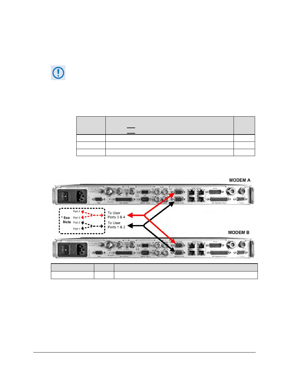
5.2.2.1.3 Quad E1 Interface Example
The G.703 Balanced and Auxiliary G.703 DB-9F single connectors are used for Quad E1
operation.
1)
As shown in Figure 5-6, the CA-0000071 ‘Y’ Cable provides for two ports of E1
(i.e., Ports 1/2 -or- Ports 3/4).
2)
If you desires three or four separate ports of E1 (i.e., Port 1 and Port 2 -or- Port
3 and Port 4), then optional adapter cables may be purchased from Comtech
EF Data to adapt the G.703 Balanced and Auxiliary G.703 DB-9F single
connector pairs to outgoing Quad E1 connector pairs as follows:
Cable
CEFD P/N
Converts (1) 9-pin Type ‘D’ (DB-9F) paired connection (e.g.,
Modem A AND Modem B G.703 Balanced connector pair –or–
Modem A AND Modem B Auxiliary G.703 connector pair) to:
See
App. A
Fig.
CA-0000163 (2) 15-pin Type ‘D’ (DB-15F) connectors
A-9
CA-0000164 (2) RJ-48 female connectors
A-10
KT-0000122
(4) BNC 75Ω female connectors – (2) Tx, (2) Rx
A-11
All three cabling options plug into the single ‘To User’ connector side of each
CA-0000071 ‘Y’ Splitter cable used.
Figure 5-6. CDM-625/A Quad E1 1:1 Example
CEFD P/N
Qty
Description
CA-0000071
2
Note 1
Cable – 1:1 ‘Y’ Splitter, (2X) DB-9M DB-9F, 8”