2 top and antenna side features – Comtech EF Data CRS-180 User Manual
Page 23
CRS-180 70/140 MHz IF 1:1 Redundancy Switch
MN/CRS180.IOM
Introduction
Revision 11
1–3
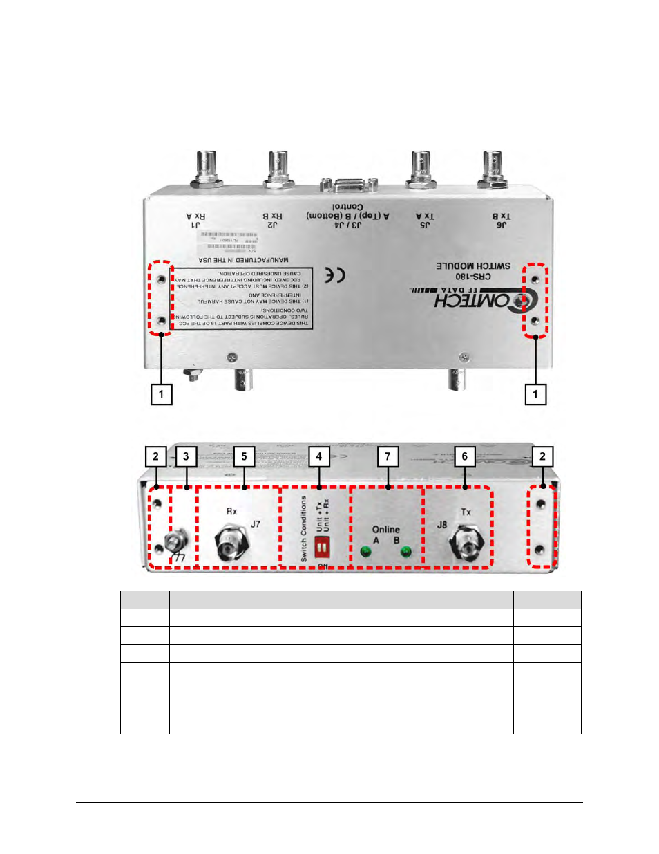
1.2.2 Top and Antenna Side Features
Figure 1-3 shows the CRS-180 top and antenna side features and the chapters that provide more
detailed information.
Feature Description
Chapter Sect.
1
4X #6-32 holes for vertical rack mounting (used for Switch Mounting Kit KT/11708)
2.2
2
4X #6-32 holes for horizontal rack mounting (used for Switch Mounting Kit KT/11708)
2.2
3
Ground Stud
2.2, 3.2.2.2
4
“Switch Conditions” DIP Switches
1.3.1, 4.6
5
J7 | Rx BNC Input Connector
3.2.2.1
6
J8 | Tx BNC Output Connector
3.2.2.1
7
Online LED Indicators
1.3.1
Figure 1-3. CRS-180 – Top and Antenna Side Features
See also other documents in the category Comtech EF Data Equipment:
- CDD-880 (124 pages)
- CDM-800 (130 pages)
- ODMR-840 (184 pages)
- CDM-750 (302 pages)
- CDM-840 (244 pages)
- SLM-5650A (420 pages)
- CTOG-250 (236 pages)
- CDM-700 (256 pages)
- CDM-760 (416 pages)
- CDM-710G (246 pages)
- CDM-600/600L (278 pages)
- CDMR-570L (512 pages)
- CDM-625 (684 pages)
- CDM-625A (756 pages)
- CDD-564A (240 pages)
- CDD-564L (254 pages)
- CLO-10 (134 pages)
- MCED-100 (96 pages)
- CDMR-570AL (618 pages)
- CDM-600 LDPC (2 pages)
- BUC Power Supply Ground Cable (2 pages)
- MPP70 Hardware Kit for CDM-570L (4 pages)
- MPP50 Hardware Kit for CDM-570L (4 pages)
- CDM-625 DC-AC Conversion (4 pages)
- CDM-625 DC-AC Conversion with IP Packet Processor (4 pages)
- DMDVR20 LBST Rev 1.1 (117 pages)
- DMD2050E (212 pages)
- DMD-2050 (342 pages)
- DMD1050 (188 pages)
- OM20 (220 pages)
- QAM256 (87 pages)
- DD240XR Rev Е (121 pages)
- MM200 ASI Field (5 pages)
- DM240-DVB (196 pages)
- MM200 (192 pages)
- CRS-150 (78 pages)
- CRS-280L (64 pages)
- CRS-170A (172 pages)
- SMS-301 (124 pages)
- CiM-25/8000 (186 pages)
- CiM-25 (26 pages)
- CRS-500 (218 pages)
- CRS-311 (196 pages)
- CIC-20 LVDS to HSSI (26 pages)