1 switch-to-modem control interface connection – Comtech EF Data CRS-180 User Manual
Page 64
CRS-180 70/140 MHz IF 1:1 Redundancy Switch
MN/CRS180.IOM
Cables and Connections
Revision 11
5–4
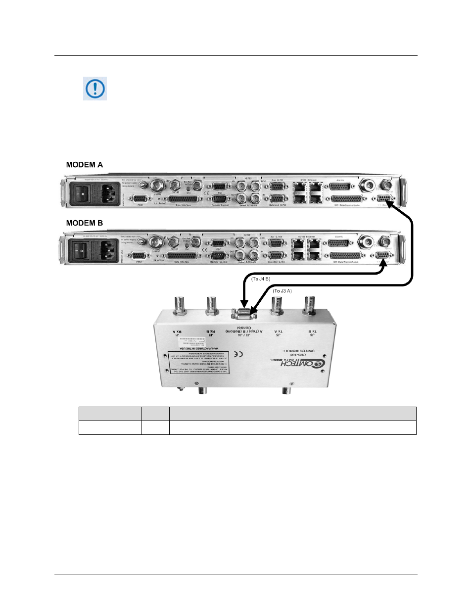
5.2.1.1 Switch-to-Modem Control Interface Connection
1)
Excluding modems, the KT-0000159 1:1 Redundancy Kit (see Sect. 5.2.1) provides
all components shown in Figure 5-1.
2)
When you connect the Control Interface cable between the CRS-180 and the
modems, make sure that you securely fasten the screw locks on the Type ‘D’
connectors. This prevents accidental disconnection of the cables, particularly
when you are removing and replacing a standby unit.
CEFD P/N
Qty
Description
CA/WR9378-4
2
Control Cable – Universal, DB-9M, 4’
Figure 5-1. CDM-625/A Switch-to-Modem Control Connections (CEFD Kit KT-0000159)
See also other documents in the category Comtech EF Data Equipment:
- CDD-880 (124 pages)
- CDM-800 (130 pages)
- ODMR-840 (184 pages)
- CDM-750 (302 pages)
- CDM-840 (244 pages)
- SLM-5650A (420 pages)
- CTOG-250 (236 pages)
- CDM-700 (256 pages)
- CDM-760 (416 pages)
- CDM-710G (246 pages)
- CDM-600/600L (278 pages)
- CDMR-570L (512 pages)
- CDM-625 (684 pages)
- CDM-625A (756 pages)
- CDD-564A (240 pages)
- CDD-564L (254 pages)
- CLO-10 (134 pages)
- MCED-100 (96 pages)
- CDMR-570AL (618 pages)
- CDM-600 LDPC (2 pages)
- BUC Power Supply Ground Cable (2 pages)
- MPP70 Hardware Kit for CDM-570L (4 pages)
- MPP50 Hardware Kit for CDM-570L (4 pages)
- CDM-625 DC-AC Conversion (4 pages)
- CDM-625 DC-AC Conversion with IP Packet Processor (4 pages)
- DMDVR20 LBST Rev 1.1 (117 pages)
- DMD2050E (212 pages)
- DMD-2050 (342 pages)
- DMD1050 (188 pages)
- OM20 (220 pages)
- QAM256 (87 pages)
- DD240XR Rev Е (121 pages)
- MM200 ASI Field (5 pages)
- DM240-DVB (196 pages)
- MM200 (192 pages)
- CRS-150 (78 pages)
- CRS-280L (64 pages)
- CRS-170A (172 pages)
- SMS-301 (124 pages)
- CiM-25/8000 (186 pages)
- CiM-25 (26 pages)
- CRS-500 (218 pages)
- CRS-311 (196 pages)
- CIC-20 LVDS to HSSI (26 pages)