2 crs-180 user connectors, 1 modem side connectors, 1 if connectors (50( bnc) – Comtech EF Data CRS-180 User Manual
Page 40: 1 if connectors (50 ω bnc)
CRS-180 70/140 MHz IF 1:1 Redundancy Switch
MN/CRS180.IOM
Switch Connectors and Pinouts
Revision 11
3–4
Connection Instructions: Press down the tab on the cable plug, and then insert the plug into the
RJ-4x jack. The connection is complete when the tab ‘clicks’ into position inside the jack.
3.2 CRS-180 User Connectors
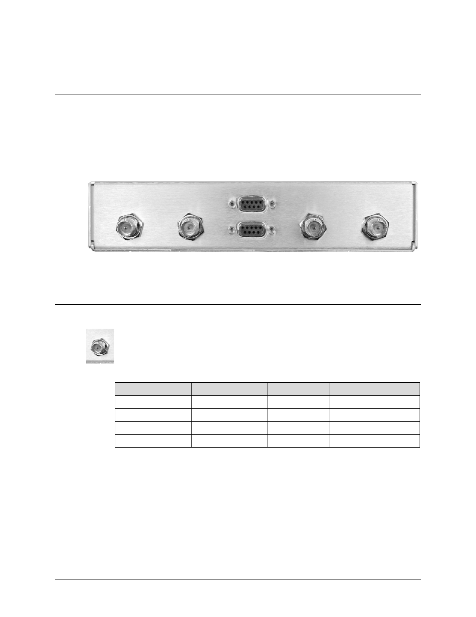
3.2.1 Modem Side Connectors
The modem side connectors (Figure 3-3) provide all necessary external connections between the
CRS-180 and the compatible Comtech EF Data modems.
J6 Tx B
J5 Tx A
J3 Control A
J4 Control B
J2 Rx B
J1 Rx A
Figure 3-3. CRS-180 – Modem Side Connectors
3.2.1.1 IF Connectors (50Ω BNC)
F
our 50Ω BNC female connectors are provided on the modem side of the CRS-180.
Table 3-1. Modem Side Type ‘BNC’ Connectors
Ref Des
Name
Connector Type
Function
J1
Rx A
BNC
IF Input to Modem ‘A’
J2
Rx B
BNC
IF Input to Modem ‘B’
J5
Tx A
BNC
IF Output from Modem ‘A’
J6
Tx B
BNC
IF Output from Modem ‘B’