1 1:1 ip redundancy data switching – Comtech EF Data CRS-180 User Manual
Page 25
CRS-180 70/140 MHz IF 1:1 Redundancy Switch
MN/CRS180.IOM
Introduction
Revision 11
1–5
keeps the Offline modem from interfering with the Rx data traffic. Send timing output from the
Offline modem is also TRI-STATE
®1
.
Manual Switching is user-enabled via the Online modem; locally using the modem’s front panel,
or remotely using serial remote control or the modem’s Web Server (HTTP) Interface.
Automatic Switching Selection is user-controlled via the Online modem.
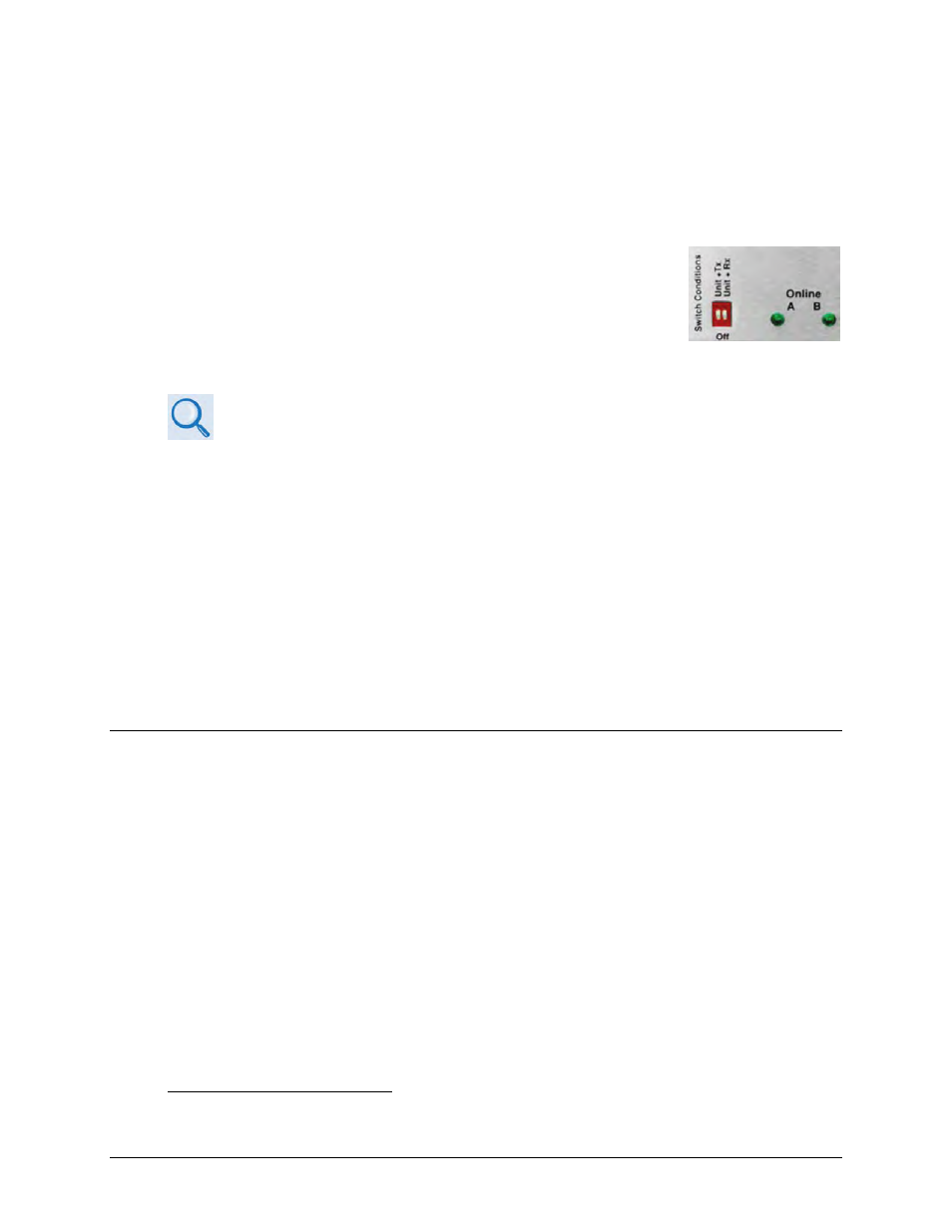
Use the CRS-180 Switch Conditions Unit+Tx and Unit+Rx DIP switches,
located on the antenna side of the CRS-180, to configure the conditions
that cause an automatic switchover. These setting provide a great deal
of flexibility in CRS-180 operation: you can select between Modem Unit
faults only; Modem Unit faults or Receive Traffic faults; Modem Unit
faults or Transmit Traffic faults; or all three.
Sect. 4.6 Configure Switch DIP Settings
Two green LEDs, located on the antenna side of the CRS-180, indicate which modem is Online.
With the ‘bridging’ architecture of the CRS-180 (whereby identical terrestrial data traffic signals
are routed to both Online and Offline modems), the redundancy controller can avoid
unnecessary switchovers. By examining the fault status of both modems, it can infer if the fault
is external to the system. For example, the CRS-180 has been configured to switch following Unit
faults or Transmit Traffic faults, and the modems have been configured for external clock
operation. Now, suppose that the external equipment (network, multiplex, router, etc.) fails –
both the Offline and Online modems will now show a Transmit Traffic fault (No Clock Detected
from Terrestrial Port). The CRS-180 Controller State Machine will see that both faults have
occurred at the same time (in fact, within a 0.5 second window), and infers that the fault is
external. Therefore, no unnecessary switchover is initiated.
1.3.1.1 1:1 IP Redundancy Data Switching
1.3.1.1.1 CDM-625/A, -760, -750, -710G, -710, -700 Managed Switch Mode
A standard, user-provided Ethernet Layer 2 switch is needed when a CDM-625/A, CDM-750,
CDM-760, CDM-710G, CDM-710 or CDM-700 modem is configured for Managed Switch Mode
(also known as “Ethernet Bridge Mode”) terrestrial traffic.
A Layer 2 switch is designed to limit the traffic that egresses each port by only sending Ethernet
packets out the port that the destination network device is located. The switch maintains a table
- known as the dynamic Content-Addressable Memory (CAM) table - that maps MAC addresses
to switch ports. When a packet arrives, in which an entry for that specific destination MAC is
unknown to the switch, it sends the packet out all ports and waits for response packets in an
attempt to identify which port that particular MAC resides. Once the device responds, the
switch is able to map the MAC to the port in the CAM table.
1
TRI-STATE is a registered trademark of National Semiconductor.