Comtech EF Data OM20 User Manual
Page 71
OM20 Universal Outdoor Modem
Rear Panel Interfaces
MN-OM20– Revision 5
5–5
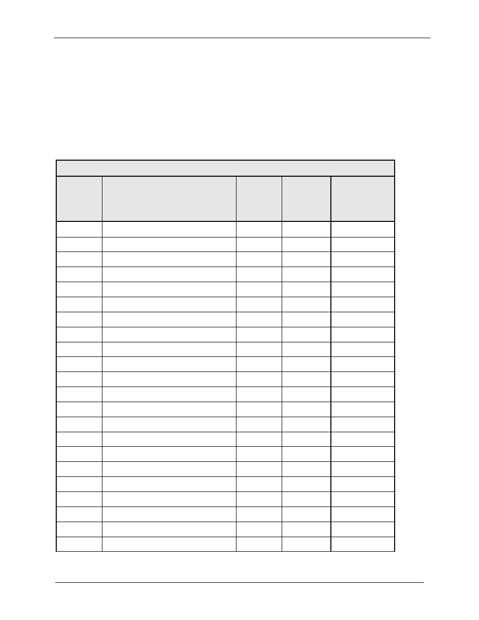
5.1.3 EIA-530 Synchronous Data, ES-ES Asynchronous Overhead Data, and G.703
Balanced Data I/O Port (J3)
This 38 Pin D38999/24FD35PN Connector contains the EIA-530 data connections (RS-
422/V.35/RS-232, the ES-ES RS485 Asynchronous Overhead data interface, the G.703 Balanced
interface, and the Open Collector Modulator and Demodulator Faults. Cable lengths up to 60
meters can be used depending on data rate, interface type, and temperature de-rating. Refer to
Table 5.4 for pin-outs.
Table 5.4. EIA-530 Synchronous Data I/O; ES-ES Async Data Connector (J3)
J3
Pin No.
Signal Name
Signal
Direction
EIA-530 Std.
25 Pin
Connector
Reference
1
Shield--- ---
1
2
Send Data B (+)
SD-B
Input
14
3
Send Data A (-)
SD-A
Input
2
4
Send Timing A (-)
ST-A
Output
15
5
Receive Data
RD-A
Output
3
6
Receive Data B (+)
RD-B
Output
16
7
Request To Send A (-)
RS-A
Input
4
8
Receive Timing A (-)
RT-A
Output
17
9
Clear To Send A (-)
CS-A
Output
5
10
Modulator Fault – Open Collector
MF
Output
18
11
Data Mode A (-)
DM-A
Output
6
12
Request To Send B (+)
RS-B
Input
19
13
Signal Ground
SGND
---
7
14
Data Terminal Ready A (-)
TR-A
Input
20
15
Receiver Ready A (-)
RR-A
Output
8
16
Demodulator Fault
DF
Output
21
17
Receive Timing B (+)
RT-B
Output
9
18
Data Mode B (+)
DM-B
Output
22
19
Receiver Ready B (+)
RR-B
Output
10
20
Data Terminal Ready B (+)
TR-B
Input
23
21
Terminal Timing B (+)
TT-B
Input
11
22
Terminal Timing
TT-A
Input
14