Ch05_rear_panel_interfaces, Chapter 5. rear panel interfaces – Comtech EF Data OM20 User Manual
Page 67
MN-OM20– Revision 5
5–1
Chapter 5. Rear Panel Interfaces
This section discusses the electrical interfaces available of the unit.
5.1
OM20 External Interface Connections
All OM20 external connections are interconnected to labeled connectors located on the front of
the unit. Any connection interfacing to the OM20 must utilize the appropriate mating connector
(supplied). Refer to Table 5.1 and Figure 5-1 for the standard unit. Reference throughout this
section will be identified as the OM20.
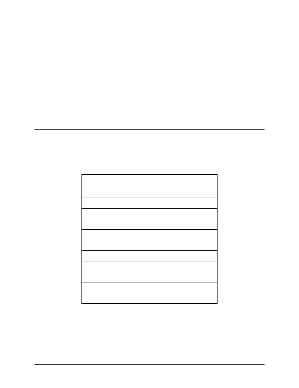
LABELS
J1 Power
J2 232/485 M&C/Terminal
J3 EIA-530 Data I/O / ES-ES Data/ Balanced G.703
J4 Ethernet (Data/M&C)
J6 Ground
J7 RX L-Band Input
J8 TX L-Band Output
J9 Compact Flash Card
J10 SD G.703 (DDI) Unbalanced, Optional ASI
J11 RD G.703 (IDO) Unbalanced, Optional ASI
J12 External Clock BNC
Table 5-1 OM20 Connection Designations
- CDD-880 (124 pages)
- CDM-800 (130 pages)
- ODMR-840 (184 pages)
- CDM-750 (302 pages)
- CDM-840 (244 pages)
- SLM-5650A (420 pages)
- CTOG-250 (236 pages)
- CDM-700 (256 pages)
- CDM-760 (416 pages)
- CDM-710G (246 pages)
- CDM-600/600L (278 pages)
- CDMR-570L (512 pages)
- CDM-625 (684 pages)
- CDM-625A (756 pages)
- CDD-564A (240 pages)
- CDD-564L (254 pages)
- CLO-10 (134 pages)
- MCED-100 (96 pages)
- CDMR-570AL (618 pages)
- CDM-600 LDPC (2 pages)
- BUC Power Supply Ground Cable (2 pages)
- MPP70 Hardware Kit for CDM-570L (4 pages)
- MPP50 Hardware Kit for CDM-570L (4 pages)
- CDM-625 DC-AC Conversion (4 pages)
- CDM-625 DC-AC Conversion with IP Packet Processor (4 pages)
- DMDVR20 LBST Rev 1.1 (117 pages)
- DMD2050E (212 pages)
- DMD-2050 (342 pages)
- DMD1050 (188 pages)
- QAM256 (87 pages)
- DD240XR Rev Е (121 pages)
- MM200 ASI Field (5 pages)
- DM240-DVB (196 pages)
- MM200 (192 pages)
- CRS-150 (78 pages)
- CRS-280L (64 pages)
- CRS-170A (172 pages)
- CRS-180 (136 pages)
- SMS-301 (124 pages)
- CiM-25/8000 (186 pages)
- CiM-25 (26 pages)
- CRS-500 (218 pages)
- CRS-311 (196 pages)
- CIC-20 LVDS to HSSI (26 pages)