4 mounting and wiring considerations – Comtech EF Data OM20 User Manual
Page 24
OM20 Universal Outdoor Modem
Installation
MN-OM20– Revision 5
2–4
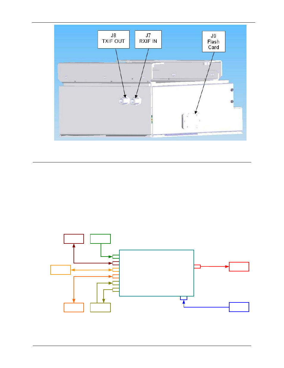
Figure 2.2a. OM 20 Rear Interconnects (cont)
2.4
Mounting and Wiring Considerations
The OM20 should be mounted with the BUC higher than the OM20 with the interconnecting
communication cabling and power cords at the lowest possible position. Unit weight and
cable/waveguide length should be considered when selecting the mounting location
The following diagrams should be used as a reference to the various mounting options. The
OM20 should not be placed immediately above a high-heat or EMI (Electro-Magnetic
Interference) source to ensure the output signal integrity and proper receive operation. Figures
2-3 through 2-11 illustrate the different interconnect and data interface configurations for the
OM20.
J
1
AC POWER
J
10
SD
(
DDI
)
J
3
EIA
-
530
INTERFACE
J
4
ETHERNET DATA
/
M
&
C
TX OUTPUT J
8
J
2 232
/
485
M
&
C
/
TERMINAL
J
11
RD
(
IDO
)
3
P
18
P
38
P
RJ
45
BNC
BNC
N
OM
-
20
RX INPUT
J
7
N
PRIME POWER
110
/
220
VAC
50
/
60
Hz
MONITOR AND
CONTROL
SYSTEM
EIA
-
530
DATA
/
M
&
C
ETHERNET
ROUTER
DATA
/
M
&
C
UNBALANCED
G
.
703
DATA I
/
O
TO BUC
/
SSPA
FROM LNB
TXRF L
-
BAND
950
–
2050
MHz
10
MHz
/+
24
VDC
RXRF L
-
BAND
950
–
2050
MHz
+
18
VDC
Figure 2-3. Outdoor Modem (OM) Interconnect Diagram