BECKHOFF BK3xx0 User Manual
Page 87

Notes on the Documentation
Fieldbus Components
85
Setting the Bus Terminal extension in the Bus Coupler
So that the same process image can always be transferred between the PROFIBUS DP master and the Bus Coupler,
independently of the implementation level of the machine or of the Bus Terminals, the maximum Bus Terminal
implementation for the Bus Coupler is always configured in the PROFIBUS DP master under multi-configuration
mode. This PROFIBUS DP configuration is sent from the PROFIBUS DP master to the Bus Coupler when the
PROFIBUS DP bus is starting up. This then compares the received PROFIBUS DP configuration with the bus
terminals that are actually present.
If the Bus Coupler is not already being operated with the maximum Bus Terminal implementation level, the
PROFIBUS DP configuration will not agree with the Bus Terminal structure that it finds. So that the Bus Coupler can
nevertheless represent the process signals from the connected Bus Terminals in the process image that is to be
exchanged with the PROFIBUS DP master, the mapping rule is now required.
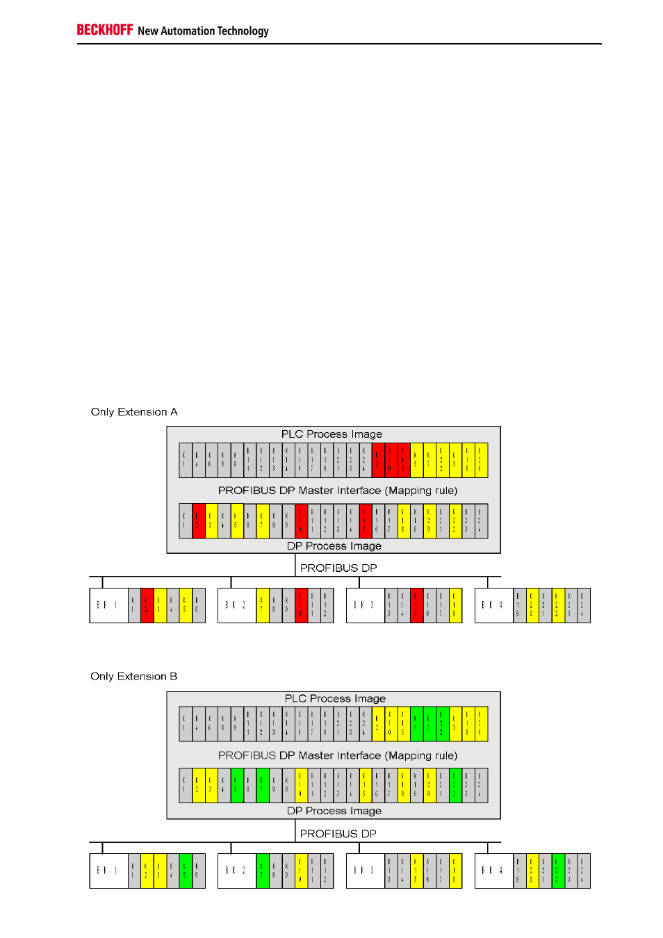
Because the Bus Coupler maps the process signals from the Bus Terminals into the DP process image according to
a fixed algorithm (first complex, then digital terminals, each in the sequence in which they are plugged in), the only
information that is missing is that of which of the Bus Terminals that are included in the PROFIBUS DP configuration
are indeed truly present. This information can be transmitted via the acyclic DPV1 Write, or through the 2-byte PLC
interface for those PROFIBUS DP master interfaces that do not support PROFIBUS DPV1. The acyclic DPV1 Write is
usually available through function blocks (TwinCAT: ADS-Write, S7 400: SFB 52 (read) and SFB53 (write)) from the
controller program. The 2-byte PLC interface of the Bus Coupler is mapped directly into the controller's process
image. As soon as a machine extension is activated or deactivated, the controller program can therefore activate or
deactivate the associated Bus Terminals.
Example as above, where deactivated terminals are marked in yellow:
