4 gpib/rs-232c command list – AMETEK SLM Series Rev B User Manual
Page 44
GPIB/RS-232 Programming Operation
SLM-Series AC/DC Electronic Load
4-2
M540072-01 Rev B
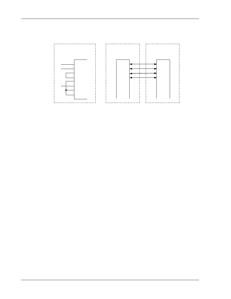
The connections for the rear panel RS-232 interface are shown below; Figure 4-1a
depicts the connector wire diagram, and Figure 4-1b depicts the connections using a
standard RS-232 cable.
RS-232C Port
On SLM Mainframe
TxD
Rxd
RTS
CTS
.
.
.
Inside the
SLM Mainframe
TxD
Rxd
RTS
CTS
DSR
GRN
DCD
DTR
PC RS-232C Port
TxD
Rxd
RTS
CTS
.
.
.
Fig. 4.1a
Fig. 4.1b
2
3
4
5
6
7
8
9
RS-232C Port
On SLM Mainframe
TxD
Rxd
RTS
CTS
.
.
.
Inside the
SLM Mainframe
TxD
Rxd
RTS
CTS
DSR
GRN
DCD
DTR
PC RS-232C Port
TxD
Rxd
RTS
CTS
.
.
.
Fig. 4.1a
Fig. 4.1b
2
3
4
5
6
7
8
9
Figure 4-1 RS-232 Interface Diagram
The following RS-232 setting commands are channel-dependent commands except
”CHAN” which is a channel-specific command; therefore, for proper program execution
”CHAN” should be sent first, and then the channel-dependent command.
For example:
Short ON of Channel 1 of SL-series Electronic Load module, the RS-232
programming command is: CHAN 1;SHOR ON.
As with the GPIB commands, the following RS-232 commands with [GLOB:] option
can set all the SL-series Electronic load modules in the SLM chassis to be active
simultaneously. This feature can greatly reduce the testing time and increase
efficiency.
4.4 GPIB/RS-232C COMMAND LIST
4.4.1
Command Syntax Abbreviations
SP
:Space, the ASCII code is 20 Hexadecimal.
;
:Semicolon, Program line terminator, the ASCII code is OA Hexadecimal.
NL
:New line, Program line terminator, the ASCII code is OA Hexadecimal.
N
:Integer from 1 to 8.
NR2 :Digits with decimal point. It can be accepted in the range and format of ##.#####.
Example: 30.12345, 5.0