AMETEK SLM Series Rev B User Manual
Page 33
SLM-Series AC/DC Electronic Load
Operation
M540072-01 Rev B
3-7
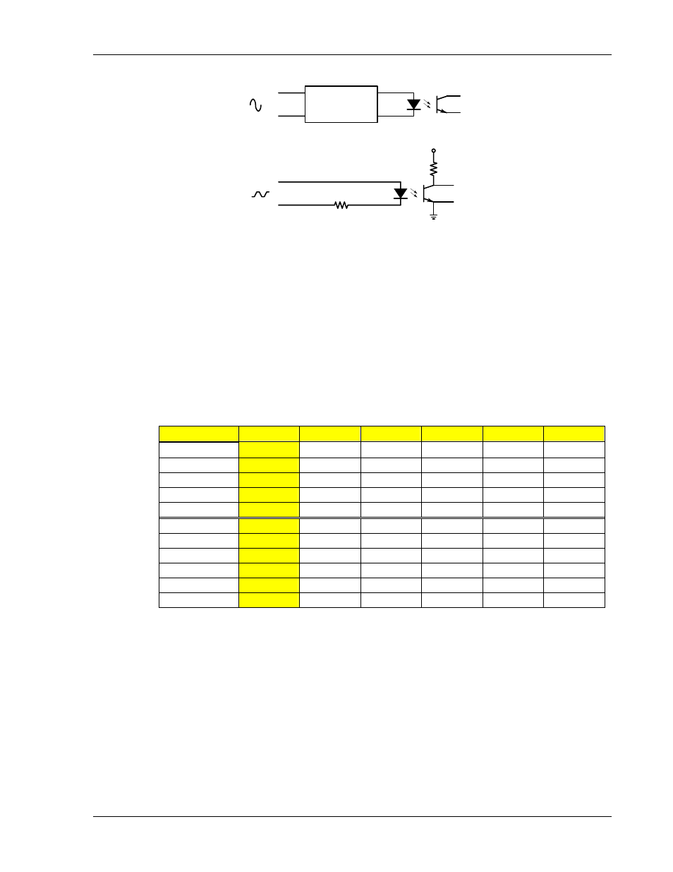
Zero Crossing
SYNC
Input
SYNC "OFF"
+5V
330Ω
SYNC
EXT+
EXT-
SYNC "ON"
Figure 3-3 Illustration of Sync
3.2.4 Crest
Factor
The SLM-Series AC/DC electronic load module provides 11 built-in sets totaling 55
waveforms.
• Select the waveforms from the memory banks. The waveforms are stored in
memory banks (0-10) with 5 selections per bank as shown in Table 3-1. (See
Appendix for waveform details).
• Select the crest factor through the √2, 2.0, 2.5, 3.0 and 3.5 keys in addition
to the bank selection.
BANK
√2
2.0
2.5
3.0
3.5
Sine Wave
0
√2 2.0 2.5 3.0 3.5
1
1.5 1.6 1.7 1.8 1.9
2
2.0 2.1 2.2 2.3 2.4
3
2.5 2.6 2.7 2.8 2.9
4
3.0 3.1 3.2 3.3 3.4
Square Wave
5
1.0 1.1 1.2 1.3 1.4
6
1.5 1.6 1.7 1.8 1.9
7
2.0 2.1 2.2 2.3 2.4
8
2.5 2.6 2.7 2.8 2.9
9
3.0 3.1 3.2 3.3 3.4
DC
10
√2dc 2dc 2.5dc 3.0dc 3.5dc
Table 3-1 Built in Crest Factor Settings by Bank andKkey Selection
• When Frequency is set to DC (see Frequency Setting above), the waveform
information shall be fixed at DC level and the “bAn” bank selection will not
appear in the FREQ key menu.
1. Press FREQ key (15). The associated LED will light. The first selection is for
frequency, as described in the section, “Frequency Setting” above.
2. Verify that the frequency does not read “dc”. If it does, use the
↑↓ keys to
adjust the frequency from “dc”.
3. Press the “FREQ” key until “bAn” appears on the upper DM.
4. Use the
↑↓ keys to select the desired bank.