AMETEK SLH Series RevB User Manual
Page 38
Operation
SLH-Series AC High Power Electronic Load
3-12
M540073-01 Rev C
3.4 STORE
/ RECALL FUNCTION AND SEQUENCE
OPERATION
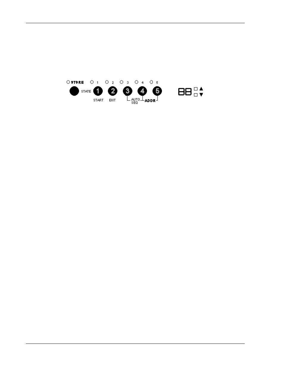
The six front panel function keys of the SLH-series High Power Load are designed for
high testing throughput. Five operation states (keys 1 through 5 in Figure 3-6) can be
stored in the non-volatile memory of SLH-series electronic load. Each state saves or
recalls the load setup, the status and the electronic load level.
Figure 3-6 STORE/RECALL and Sequencing Keypad
3.4.1 STORE
Procedure:
The STORE function stores up to five states of SLH-series load settings. If you store
2 different states in the same state key, the most recent input will replace the
previous state.
a. Set the load status and the load level from load module.
b. Press the STORE key to start the store process; its LED begins flashing.
You have ten seconds to select and press a STATE key (next) in which to
store the status and level that you’ve set.
c. Press one of the STATE 1-5 keys; the corresponding LED will light, the load
status and level of the load are stored into the non-volatile memory. Once the
STORE procedure is complete, the STORE LED is no longer lit.
Notes:
If more than one state is stored in the same State key, the last one entered will be
treated as an update and will overwrite the previously input state.
After pressing the STORE key, the front panel keys on the SL-series electronic load
module are still active. However, the STATE LED will turn off if any key on any load
module is pressed. This indicates that the front panel state of the load module is
not the same as stored state.
3.4.2 RECALL
Procedure
Press one of the STATE 1 through 5 keys to recall the stored state; its corresponding
LED will be lit.
3.4.3
AUTO SEQUENCE Procedures
There are two modes that can be activated while in AUTO SEQUENCE: EDIT MODE
and TEST MODE. To enter AUTO SEQUENCE, simultaneously press STATE KEYS 3
and 4 (S3 and S4). To activate EDIT MODE, press the STORE key. To enter TEST
MODE, press the START key. Please refer to the flow chart in Figure 3-7. A brief
description of each mode follows the flow chart.