User manual ametek programmable power rs series 72, 4 program menu – AMETEK RS Series User Manual
Page 72
User Manual
AMETEK Programmable Power
RS Series
72
OUTPUT CAL
VOLT FS
VOLT ZERO
PHASE OFST
IHARM FS
IMP. REAL FS
IMP. REACT FS
IMP. REAL MIN
IMP. REACT MIN
PREVIOUS SCREEN
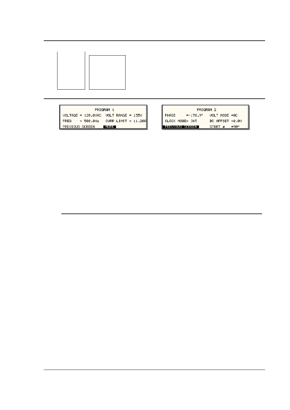
4.2.4 PROGRAM Menu
Figure 4-8: PROGRAM Menu
The PROGRAM menu is shown in Figure 4-8. It can be reached in one of two ways:
1. by selecting the PROGRAM entry in the MENU screen and pressing the ENTER key
2. by pressing the PROG key in the FUNCTION keypad
The PROGRAM menu is used to change output parameters. The most commonly used
parameters are all located in PROGRAM 1. The PREVIOUS SCREEN entry, when selected, will
return the user to the most recently selected menu. This is normally the MENU screen unless
the PROGRAM menu was selected using the PROG key on the FUNCTION keypad. Less
frequently used parameters are located in PROGRAM 2, which can be reached from the
PROGRAM 1 screen using the MORE selection, or by pressing the PROGRAM key twice.
The following choices are available in the PROGRAM menus:
Entry
Description
PROGRAM 1
VOLTAGE
Programs the output voltage in Vrms while in AC mode or
absolute voltage when in DC mode. In DC mode, negative
values can be entered.
FREQ
Programs the output frequency when in AC mode. If the unit is
in DC mode, the value for FREQ will be set to DC and cannot
be changed until AC mode is selected. When in AC mode, the
frequency can be changed from 16 Hz to 500 Hz. Values
entered that fall outside this range will generate a -200 RANGE
ERROR and will not be accepted.
VOLT RANGE
Selects 150V, 300V or optional 400V range in AC mode and
200V or 400V range in DC mode. The actual range values may
be different depending on the configuration. The value of this
field can only be changed with the shuttle or the +/- key.
CURR LIMIT
Sets the current limit value for the current detection system.
When the load current value exceeds the set current limit, a
fault condition is generated. The actual response of the AC
Source to a current limit fault is determined by the protection
mode selected in the CONFIGURATION menu. (CC = Constant
Current, CV = Constant Voltage).