AMETEK RS Series User Manual
Page 42
User Manual
AMETEK Programmable Power
RS Series
42
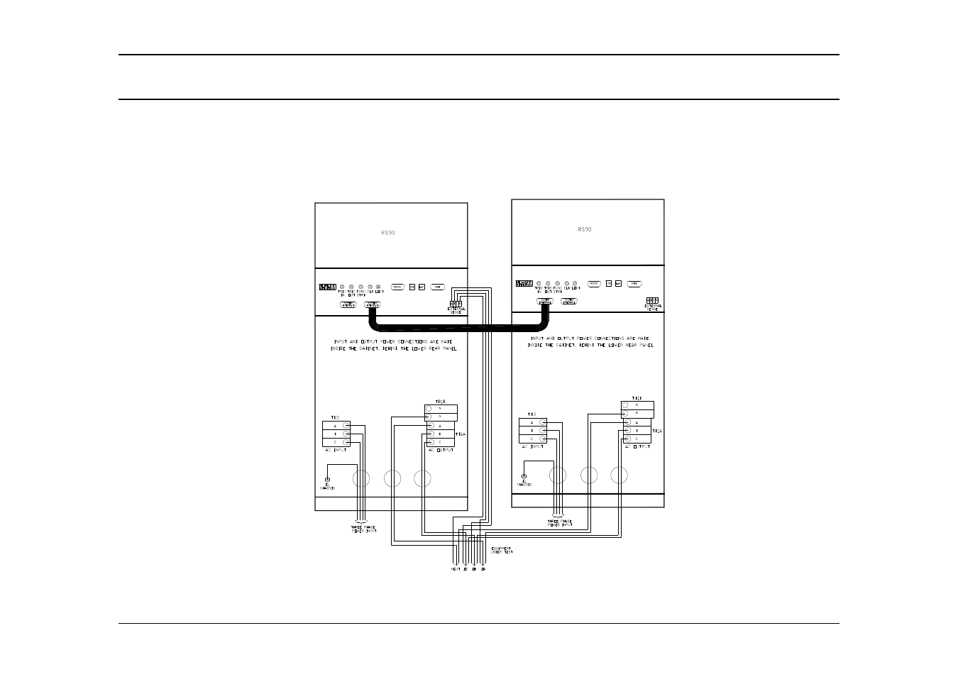
3.5.3 RS180 Parallel Output Wiring Diagram
Figure 3-8 shows the required output connections for a RS180 dual chassis parallel mode output configuration (rear view). Always
disconnect all input power from the RS90 before removing the rear panel cover that provides access to the input and output terminal
connections. RS180 systems are shipped with external output terminal blocks that enable the output wiring from two chassis to be
combined, providing a single point of connection to the EUT. These blocks must be installed in a suitable safety enclosure. It is important
to match the length of the output wiring to the common output terminal block to ensure current sharing between the two RS90 power
supplies. Additional RS90’s can be paralleled in the same way to create higher power configurations.
Figure 3-8: RS180 or RS180-MB Output Wiring (Rear view)
- CW-M (48 pages)
- CW-M Corrected Table 4-2 in (1 page)
- CW-P (62 pages)
- Lx Series (205 pages)
- CW Series Programming Manual (25 pages)
- Ls Series II Programming Manual (242 pages)
- Compact i/iX Series (157 pages)
- Compact IX 2253 (157 pages)
- Compact i/iX Series Software Manual (203 pages)
- ASD Series Quick Start (5 pages)
- ASD Series (120 pages)
- i-iX Series II Programming Manual (226 pages)
- DLM 600W Series Programming Manual (24 pages)
- M131 Programming Manual (99 pages)
- DLM Series (74 pages)
- DLM 600W Series (82 pages)
- BPS Series (153 pages)
- DLM600 Series (16 pages)
- DCS-E 1.2kW Series (65 pages)
- DLM-E 4kW Series Programming Manual (32 pages)
- M136 (8 pages)
- DCS-E 3kW Series (94 pages)
- CTS 3.0 (166 pages)
- CSW Series (174 pages)
- 2003RP (126 pages)
- 2001RP (131 pages)
- MX CTSH (151 pages)
- MXCTSL Administrator Manual (27 pages)
- MX CTSL (157 pages)
- MX Series Installation Manual (35 pages)
- Ls AC source (2 pages)
- MX15 Series (184 pages)
- Ls Series II (226 pages)
- Lx Series Driver Manual (275 pages)
- MX Series Rev: AY (257 pages)
- iX Series (341 pages)
- i-iX Series II (258 pages)
- GUPS 2400A-108 (36 pages)
- HPD Series (58 pages)
- HPD Series Operation Manual (41 pages)
- HPD Series GPIB-Multichannel (134 pages)
- PLA-PLW Programming Manual (74 pages)
- ReFlex Mating Connnectors for Controller (3 pages)
- LPDC-16V (4 pages)