AMETEK RS Series User Manual
Page 147
User Manual
AMETEK Programmable Power
RS Series
147
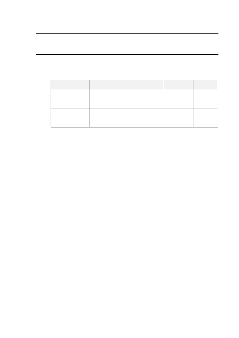
6.3.3 Measurement Calibration Summary
The following Table is a summary of the preceding calibration steps. The value indicated by the
External DVM is called V
AC
or V
DC
. The current measured by the current shunt is called I
AC
or
I
DC
.
TITLE
PROGRAM/LOAD PARAMETERS
PARAMETER
ADJUST TO
AC MODE
AC Volt Full-scale
300 VAC Range, 240 VAC, 60 Hz, no load
VOLT FS
V
AC
AC Current Full-scale
150 VAC Range, 120 VAC, 60 Hz, full load
to 90% of max current range.
CURR FS
I
AC
DC MODE
DC Volt + Full-scale
400 VDC Range, + 320 VDC, no load
VOLT FS
V
DC
DC Current Full-scale
200 VDC Range, 160 VDC, full load to 90%
of max. current range.
CURR FS
I
DC
Table 6-2: Measurement Calibration Table - TBD
Repeat Paragraph 6.3 for each phase. Move the external test equipment to the phase that is
being calibrated. Refer to Figure 6-2..
While viewing the calibration screen, press the PHASE key to select the respective phase.
- CW-M (48 pages)
- CW-M Corrected Table 4-2 in (1 page)
- CW-P (62 pages)
- Lx Series (205 pages)
- CW Series Programming Manual (25 pages)
- Ls Series II Programming Manual (242 pages)
- Compact i/iX Series (157 pages)
- Compact IX 2253 (157 pages)
- Compact i/iX Series Software Manual (203 pages)
- ASD Series Quick Start (5 pages)
- ASD Series (120 pages)
- i-iX Series II Programming Manual (226 pages)
- DLM 600W Series Programming Manual (24 pages)
- M131 Programming Manual (99 pages)
- DLM Series (74 pages)
- DLM 600W Series (82 pages)
- BPS Series (153 pages)
- DLM600 Series (16 pages)
- DCS-E 1.2kW Series (65 pages)
- DLM-E 4kW Series Programming Manual (32 pages)
- M136 (8 pages)
- DCS-E 3kW Series (94 pages)
- CTS 3.0 (166 pages)
- CSW Series (174 pages)
- 2003RP (126 pages)
- 2001RP (131 pages)
- MX CTSH (151 pages)
- MXCTSL Administrator Manual (27 pages)
- MX CTSL (157 pages)
- MX Series Installation Manual (35 pages)
- Ls AC source (2 pages)
- MX15 Series (184 pages)
- Ls Series II (226 pages)
- Lx Series Driver Manual (275 pages)
- MX Series Rev: AY (257 pages)
- iX Series (341 pages)
- i-iX Series II (258 pages)
- GUPS 2400A-108 (36 pages)
- HPD Series (58 pages)
- HPD Series Operation Manual (41 pages)
- HPD Series GPIB-Multichannel (134 pages)
- PLA-PLW Programming Manual (74 pages)
- ReFlex Mating Connnectors for Controller (3 pages)
- LPDC-16V (4 pages)