AMETEK RS Series User Manual
Page 60
User Manual
AMETEK Programmable Power
RS Series
60
3.12 Junction Box Accessory TBD
An optional wiring junction box (P/N 7003-416-1) is available which may be used to connect the
outputs of 2 to 6 RS cabinets together. The junction box also has a protective ground
connection, which MUST be connected to a suitable protective earth ground.
Each junction box has four sets of terminals for phase A, phase B, phase C and Neutral. Each
terminal is lined up with a strain relief on each side. The outputs from the RS90 cabinets connect
to the “RS SYSTEM OUTPUT” side of these terminal blocks. The load can be connected to the
“LOAD”. Note that the wiring is not supplied with the system and must be provided by the end
user. The wire gauge of the load connection must be sized to handle the maximum current in the
low voltage range of operation.
The “RS SYSTEM OUTPUT” side of the terminal block will accept up to 8 wires. If the external
sense connection is made at the junction box, one of these can be used to connect the sense
wiring.
Note: Do not swap output load wires or sense wires between phases, as damage to the system
will result.
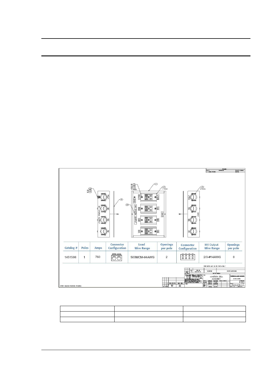
The “LOAD” side will accept 2 wires. The wire size range shown in Figure 3-15 refers to
mechanical compatibility of terminal block only. This information does not reflect required wire
size. The wire sizes accepted by the terminal blocks of the junction box on each side are shown
in Figure 3-15.
Figure 3-15: 7003-416-1 Output Junction Box
Dimensions 7003-416-1:
W x L x H Chassis
12.125 “ x 16.125” x 4.125”
308 x 410 x 105 mm
Feet height:
0.875
22 mm
Strain relief hole size:
1.5” diameter
38 mm diameter