AMETEK RS Series User Manual
Page 13
User Manual
AMETEK Programmable Power
RS Series
13
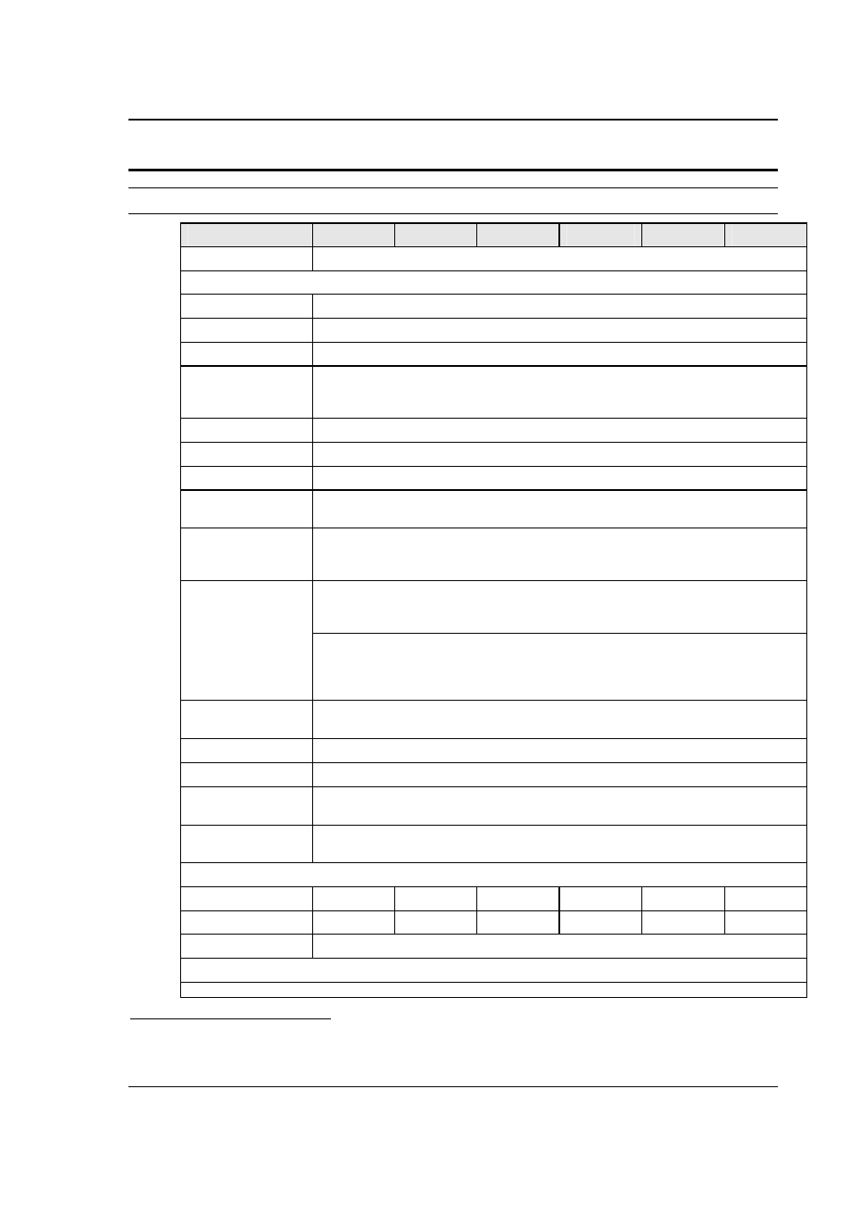
2.1.2 Output
Note: All specifications are for AC and DC unless otherwise indicated.
Output Parameter
RS90
RS180
RS270
RS360
RS450
RS540
Modes
AC, DC, AC+DC
Voltage:
Ranges (L-N):
AC Mode
Low: 0 - 150 V / High: 0 - 300 V
DC Mode
Low: 0 - 200 V / High: 0 - 400 V
AC+DC Mode
AC: Low: 0 - 150 V / High: 0 - 300 V
DC Offset: Low Vrange: 0 - 150 V
High Vrange: 0 - 220 V
Resolution:
AC Mode
0.1 V
DC Mode
0.1 V
AC+DC Mode
AC:
0.1 V
DC Offset:
0.01 V
Accuracy:
± 0.3 V < 100Hz, ± 0.6 V > 100Hz, AC mode
± 1 V DC mode
From 5% Vrange to 100% of Vrange, RMS bandwidth < 10KHz
Distortion THD
1
:
(Resistive full load,
normal mode)
< 0.5 % @ 16 - 66 Hz
< 1.00 % @ 66 - 500 Hz
< 1.25 % @ > 500 Hz
Distortion THD
1
:
(Resistive full load,
Regenerative
mode (-SNK))
< 1 % @ 16 - 66 Hz
< 2 % @ 66 - 500 Hz
< 3 % @ > 500 Hz
Load Regulation:
0.25 % FS @ DC - 100 Hz
0.5 % FS @ > 100 Hz
Line Regulation:
0.1% for 10% input line change
DC Offset Voltage:
< 20 mV
Output Noise:
(20 kHz to 1 MHz)
< 2 V
RMS
low V Range
< 3 V
RMS
high V Range
Output Coupling
DC coupled
Except on optional -HV or -XV Voltage range output, which is AC coupled.
Power (total power for all phases, either range, at full scale voltage, maximum ambient T = 35° C)
AC Mode
90 KVA
180 KVA
270 KVA
360 KVA
450 KVA
540 KVA
DC Mode
60 KW
120 KW
180 KW
240 KW
300 KW
360 KW
AC+DC Mode
The maximum power and current in the AC+DC mode is equal to that in the DC mode
Current
Note: Current, maximum amps indicated per phase available between 50 and 100 % of voltage range.
1
The distortion specification for the RS Series is valid for pure (inductance < 12 uH) resistive load conditions and
using a 30 KHz LP filter on distortion meter.