Paxton Superchargers Ford Mustang GT User Manual
Page 47
P/N: 4809654 v5.0
©2010 Paxton Automotive
All Rights Reserved, Intl. Copr. Secured
27
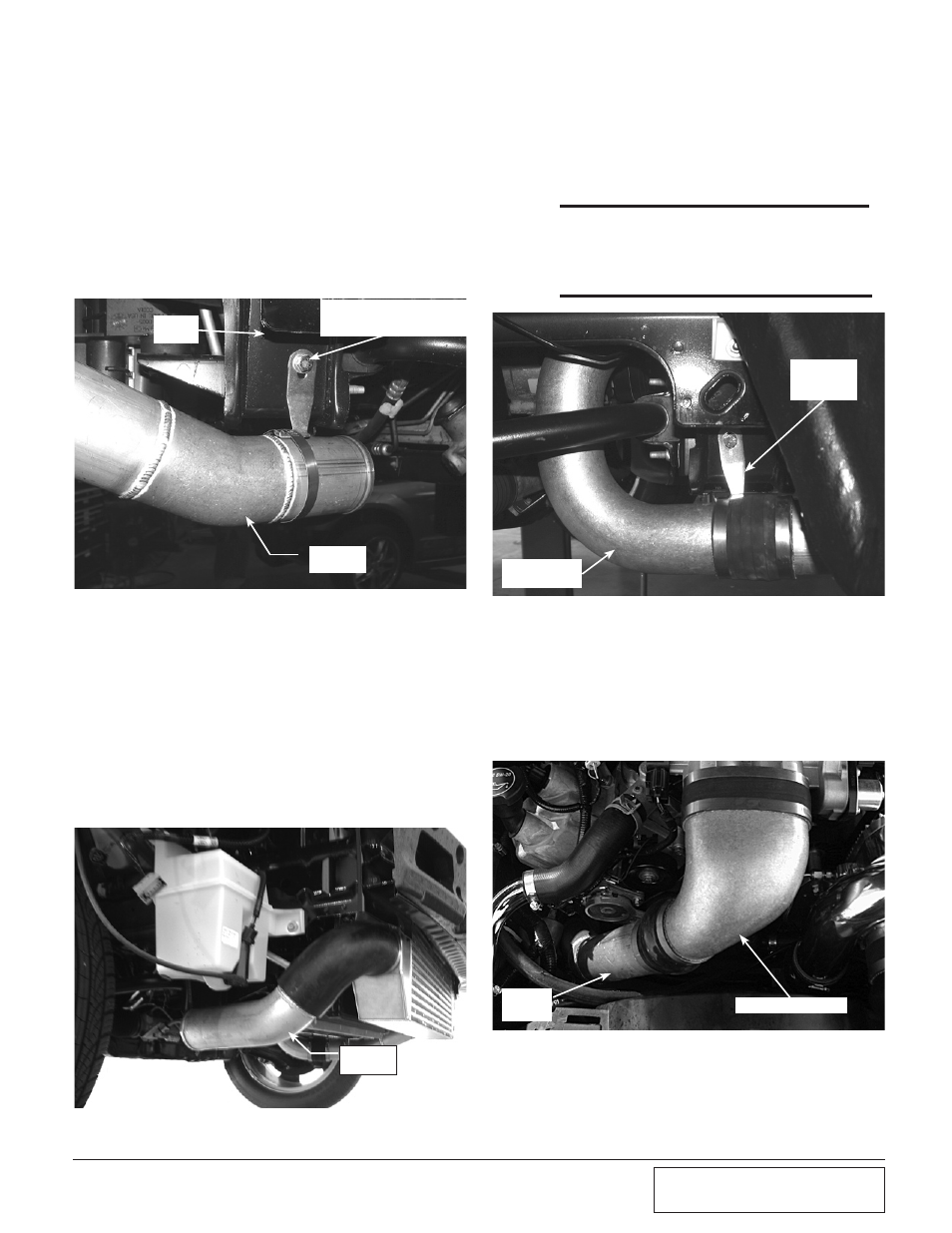
8B. CHARGE AiR CooLER CoRE iNSTALLATioN
(2005-2006 H.o. kits only), cont’d
Fig. 8B-e | Driver’s side
Fig. 8B-g | Passenger’s side
Fig. 8B-f
Fig. 8B-h
5. Install the provided 3" x 3" sleeve and #48 hose
clamps onto the open end of tube “B”.
6. Using a 5/16-18 tap, tap the lower hole on the
driver’s and passenger’s side core support.
Locate the tube support brackets, 5/16-18 x 1/2"
screws and washers. Loosely attach the tube
support brackets to the core support. (See Fig.
8B-e, 8B-g.)
7. Install tube “C” between the 90° rubber elbow
and the 3" x 3" sleeve previously installed on
tube “B”. Attach tube “C” to its support bracket
using the #44 hose clamp. Tighten the clamp
and bracket. Secure all hose connections to this
point using the #48 hose clamps provided
adjusting for best fit and clearance.
8. Install the short end of tube “D” into the open
end of the passenger’s side 90° rubber elbow
previously install. (See Fig. 8B-f.)
9. Attach a 3" x 3" sleeve and #48 hose clamps to
the open end of tube “D”.
10. Install the short end of tube “E” into the sleeve
attached to tube “D”. Secure the tube support
bracket using the previously installed #48 hose
clamp. (See Fig. 8B-g.)
*** NOTE ***
For better fit, the transmission cooler lines (if
equipped) will need to be pushed upward slightly so
that tube “E” will fit between them and the A/C com-
pressor. (See Fig. 8B-g.)
11. Attach the cast discharge duct to the throttle
body using the supplied 4.5" sleeve and #72
hose clamps.
12. Using the remaining 3" x 3" bump sleeve and
#48 hose clamps, connect the long end of tube
“E” to the cast discharge tube. (See Fig. 8B-h.)
13. Secure all hose connections at this time, adjust-
ing for best fit and clearance.
TUBE
“C”
UPPER
HOLE
LOWER HOLE TAPPED
WITH BRACKET
INSTALLED
TUBE
“D”
TUBE
“E”
DISCHARGE DUCT
TUBE
SUPPORT
BRACKET
SHORT END
OF TUBE “E”