Paxton Superchargers Ford Mustang GT User Manual
Page 23
P/N: 4809654 v5.0
©2010 Paxton Automotive
All Rights Reserved, Intl. Copr. Secured
3
Fig. 1-j
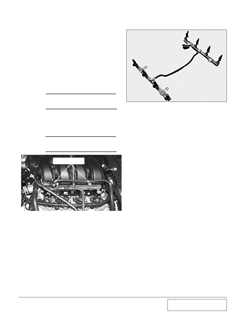
Fig. 1-i
8mm HEADED
SCREWS
1. PREPARATioN/REMovAL,
cont’d
P. Using a 1/2" ratchet, release the tension from
the accessory drive belt and remove it from the
car. This drive belt will be replaced with a lon-
ger one later in the installation.
vacuum line from the fuel regulator.
Remove the rails and injectors as a com-
plete unit and set aside. New injectors will
be installed in a later step. (See Figs. 1-i,
1-j.)
4. Locate and remove the remaining 10mm
headed bolts retaining the intake manifold
to the cylinder heads. There are
five on
each side.
5. (2005-2006 Only): Remove the intake
manifold and set aside so it can be rein-
stalled after modifications to the coolant
crossover tube are made.
6. (2007-2010 Only): It is not necessary to
remove the intake manifold from the vehi-
cle completely. Raise the front of the man-
ifold 3-4" and support between the throt-
tle-body and alternator.
*** NOTE ***
Modification to the crossover tube will be com-
pleted in a later step
*** NOTE ***
Modification to the crossover tube will be com-
pleted in a later step