Chipset, North bridge configuration – NEXCOM OPPC 1520T User Manual
Page 100

Copyright © 2011 NEXCOM International Co., Ltd. All Rights Reserved.
85
Chapter 4: BIOS Setup
OPPC 1520T/1720T User Manual
Chipset
This section is used to configure the system based on the specific features
of the chipset.
Setting incorrect field values may cause the system to malfunc-
tion.
BIOS SETUP UTILITY
Exit
v02.61 (C)Copyright 1985-2006, American Megatrends, Inc.
← →
Select Screen
↑↓
Select Item
Enter Go to Sub Screen
F1
General Help
F10 Save and Exit
ESC Exit
Boot
Security
Main
Advanced
Chipset
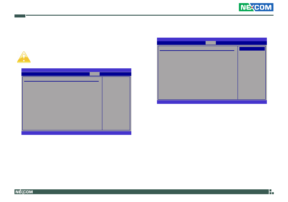
Configure North Bridge
features.
Advanced Chipset Settings
WARNING: Setting wrong values in below sections may cause system
to malfunction.
u
North Bridge Configuration
u
South Bridge Configuration
BIOS SETUP UTILITY
v02.61 (C)Copyright 1985-2006, American Megatrends, Inc.
← →
Select Screen
↑↓
Select Item
+-
Change Option
F1
General Help
F10 Save and Exit
ESC Exit
North Bridge Chipset Configuration
PCI MMIO Allocation:
4GB to 3072MB
Internal Graphics Mode Select
[Enabled, 8MB]
PEG Port Configuration
DVMT Mode Select
[DVMT Mode]
DVMT/FIXED Memory
[256MB]
Boot Display Device
[CRT + LVDS]
Flat Panel Type
[1024x768 18bit S]
LVDS Backlight Control
[100%]
Chipset
North Bridge Configuration
Options
Fixed Mode
DVMT Mode
DVMT Mode Select
Selects the DVMT mode.
DVMT/Fixed Memory
This field is used to select the graphics memory size used by DVMT/Fixed
mode. The options are 128MB, 256MB and Maximum DVMT.
LVDS Backlight Control
Configures the LVDS backlight. The options are 40%, 60%, 80% and
100%.
