CIRCUTOR CIRLAMP Series User Manual
Page 80
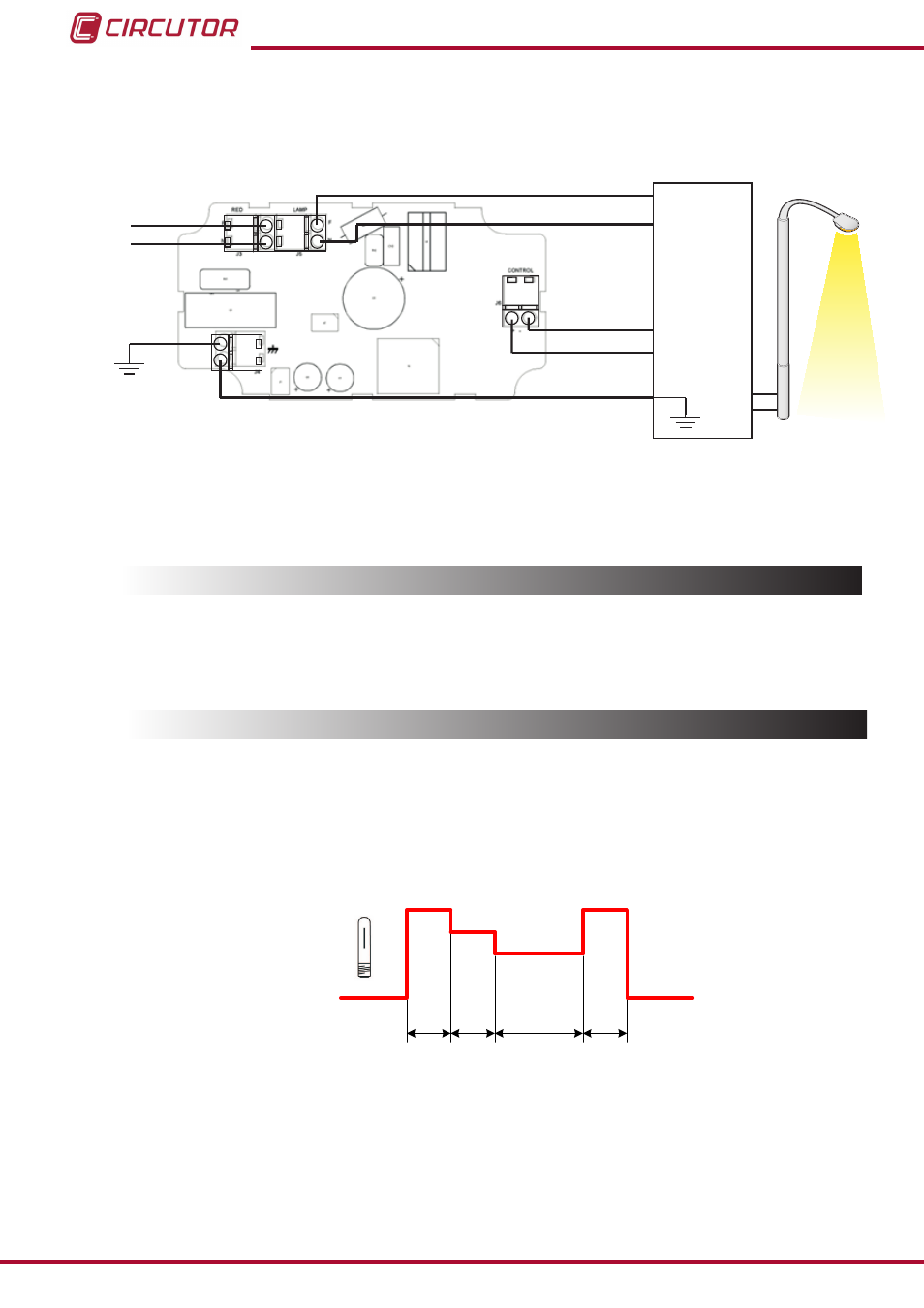
6�1�4� CONNECTION DIAGRAM
J3
J4
J5
J6
L
N
L
L
N
N
Control
1...10V
Balasto
Alimentación
+
-
-
+
Power supply
Ballast
Figure 88:Connection diagram CirLAMP Node 1 ��� 10V�
6.2.- CONNECTION WITH CirLAMP MANAGER
The connection with the
CirLAMP Manager is performed via the electrical network using PLC
technology. (see
6.3.- OPERATION
6�3�1� WORK INTERVALS
The
CirLAMP Node 1 ��� 10V connects to a 1 to 10 V control ballast, where four different work
intervals can be defined.
Each work interval is defined by the value of the outlet power and the interval time period.
T1
T2
T3
T4
100%
75%
50%
0%
Figure 89:Operation of a 1 to 10V ballast�
shows an example of operation with a 1 to 10V ballast or driver:
On powering, the unit begins to work delivering 100% of the power to the lamp during the de-
fined time T1.
Once this time has elapsed, interval T2 begins, where the power fed to the lamp is reduced to
75%, applying the corresponding control voltage to the 1 to 10V ballast.
80
CirLAMP system
Instruction Manual