Power measurement, Power measurement –48 – Altera Cyclone IV GX FPGA Development Board User Manual
Page 56
2–48
Chapter 2: Board Components
Power Supply
Cyclone IV GX FPGA Development Board
May 2013
Altera Corporation
Reference Manual
lists the power supply component reference and manufacturing
information.
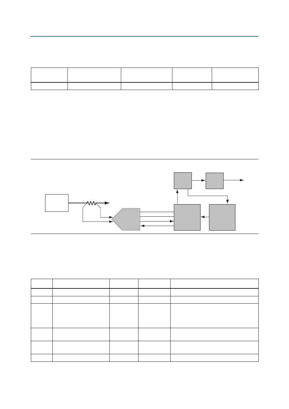
Power Measurement
There are eight power supply rails which have on-board voltage and current sense
capabilities. The power supply rails are split from the primary supply plane by a
low-value sense resistor for the 8-channel differential input 24-bit ADC device to
measure voltage and current. A SPI bus connects the ADC device to the MAX II CPLD
EPM2210 System Controller.
shows the block diagram for the power measurement circuitry.
lists the targeted rails. The schematic signal name column specifies the
name of the rail being measured and the device pin column specifies the devices
attached to the rail. If no subnet is named, the power is the total output power for that
voltage.
Table 2–44. Power Supply Component Reference and Manufacturing Information
Board Reference
Description
Manufacturer
Manufacturing
Part Number
Manufacturer
Website
—
16-V power supply
EDAC Power Electronics
EA1060A
.edac.com.tw
Figure 2–8. Power Measurement Circuit
SCK
DSI
DSO
CSn
8 Ch.
To Plane
Supply
R
SENSE
EPM2210
EP4CGX150
LTC2418
EPM
240
USB
PHY
To User PC
Power GUI
JTAG Chain
SPI Bus
Embedded
USB-Blaster
U36
Table 2–45. Power Rails Measurement Based on the Rail Selected in the Power GUI (Part 1 of 2)
Rail
Schematic Signal Name
Voltage (V)
Device Pin
Description
1
1.8V_B3_B4
1.8
VCCIO
1.8-V power to banks 3 and 4
2
1.8V_B7_B8
1.8
VCCIO
1.8-V power to banks 7and 8
3
2.5V_B5_B6
2.5 or 1.8
VCCIO
1.8-V or 2.5-V power to banks 5 and 6.
Voltage selected by jumper J3. When J3 is
shunted the voltage is 2.5 V and not shunted it
is 1.8 V
4
VCCA
2.5
VCCA,
VCC_CLKIN
PLL analog power
5
2.5V_VCCA_VCCH_GXB
2.5
VCCA_GXB,
VCCH_GXB
Transceiver buffer power
6
1.2V_VCCL_GXB
1.2
VCCL_GXB
PMA auxiliary power