Setup elements, Board settings dip switch, Setup elements –17 – Altera Cyclone IV GX FPGA Development Board User Manual
Page 25: Board settings dip switch –17
Chapter 2: Board Components
2–17
Configuration, Status, and Setup Elements
May 2013
Altera Corporation
Cyclone IV GX FPGA Development Board
Reference Manual
lists the board-specific LEDs component references and manufacturing
information.
Setup Elements
The development board includes several different kinds of setup elements. This
section describes the following setup elements:
■
Board settings DIP switch
■
JTAG chain select DIP switch
■
PCIe control DIP switch
■
Configuration push buttons
■
System reset push button
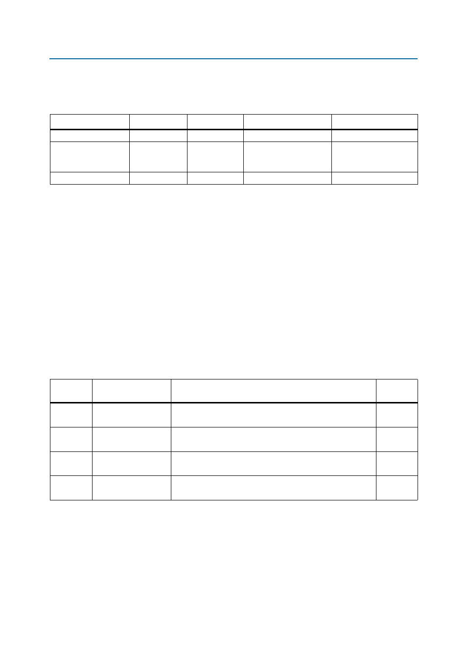
Board Settings DIP Switch
The board settings DIP switch (S1) controls various features specific to the board and
the MAX
II CPLD EPM2210 System Controller logic design.
shows the
switch controls and descriptions.
Table 2–9. Board-Specific LEDs Component References and Manufacturing Information
Board Reference
Description
Manufacturer
Manufacturer Part Number
Manufacturer Website
D17, D18
Red LED
Lumex, Inc.
SML-LXT0805IW-TR
D1, D2, D11, D16,
D19–D22, D24–D27,
D30, D31
Green LEDs
Lumex, Inc.
SML-LXT0805GW-TR
D11
Blue LED
Lumex, Inc.
SML-LX1206USBC-TR
Table 2–10. Board Settings DIP Switch Controls
Board
Reference
Schematic Signal Name
Description
SW1.1
USER_FACTORY
ON : Factory image
OFF : User image
ON
SW1.2
CLK125_EN
ON : 125-MHz clock enabled
OFF : 125-MHz clock disabled
ON
SW1.3
CLKA_EN
ON : On-Board oscillator enabled
OFF : On-Board oscillator disabled
ON
SW1.4
CLKA_SEL
ON : 100-MHz oscillator input select
OFF : SMA input select
ON
Note to
:
(1) ON indicates a setting of ’0’ while OFF indicates a setting of ’1’.