Max ii cpld epm2210 system controller, Max ii cpld epm2210 system controller –7 – Altera Cyclone IV GX FPGA Development Board User Manual
Page 15
Chapter 2: Board Components
2–7
MAX II CPLD EPM2210 System Controller
May 2013
Altera Corporation
Cyclone IV GX FPGA Development Board
Reference Manual
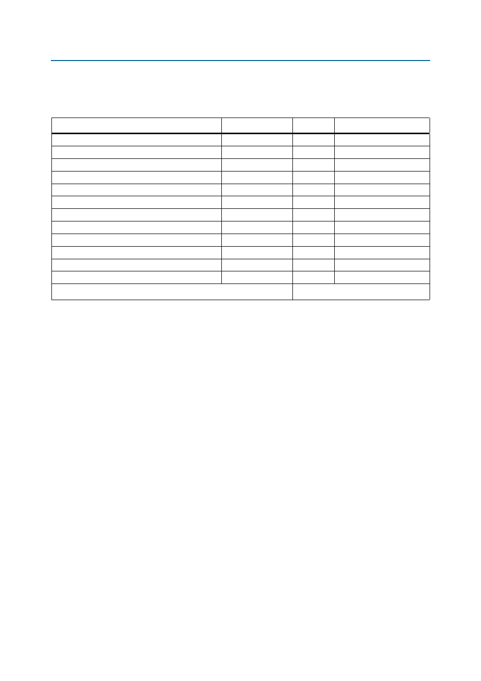
lists the Cyclone IV GX device pin count and usage by function on the
development board.
MAX II CPLD EPM2210 System Controller
The board utilizes the EPM2210 System Controller, an Altera MAX
II CPLD, for the
following purposes:
■
FPGA configuration from flash memory
■
Power consumption monitoring
■
Virtual JTAG interface for PC-based GUI
■
Control registers for clocks
■
Control registers for remote system update
Table 2–4. Cyclone IV GX Device I/O Pin Count and Usage
Function
I/O Standard
I/O Count
Special Pins
Clocks or Oscillators
1.8-V CMOS
9
3 clock inputs, 1 clock input
DDR2A x32 (Top)
1.8-V SSTL
63
—
DDR2B x32 (Bottom)
1.8-V SSTL
63
—
Flash, SSRAM, MAX
1.8-V CMOS
55
—
Gigabit Ethernet
2.5-V CMOS
16
—
User I/O (LEDs, Push buttons)
1.8-V
25
—
14-pin LCD
2.5-V CMOS
11
—
HSMC Port A
2.5-V/1.8-V CMOS
103
—
HSMC Port B
2.5-V CMOS
87
—
PCIe x4
2.5-V CMOS
7
—
PCIe (for HSMC port B transceiver multiplexer)
XCVR
16
—
Passive serial and active serial configuration
2.5-V CMOS
21
—
Device I/O Total:
476
Note to
:
(1) Translated from 1.8-V to 2.5-V using a bidirectional voltage translator.