Power distribution system, Power distribution system –26 – Altera Transceiver Signal Integrity Development Kit, Stratix IV GT Edition User Manual
Page 36
2–26
Chapter 2: Board Components
Power
Transceiver Signal Integrity Development Kit,
November 2011
Altera Corporation
Stratix IV GT Edition Reference Manual
lists the connection of this power switch.
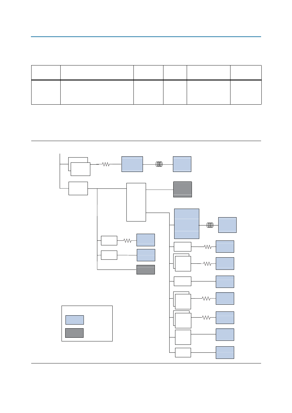
Power Distribution System
shows the power distribution system on the board.
Table 2–29. Slide Switch Pin-Out (SW1)
Board
Reference
Description
Schematic
Signal Name
I/O
Standard
Stratix IV GT Device
Pin Name
Other
Connections
SW1
Power switch. Slide switch to ON
position to power on the board. Slide
switch to OFF position to power off
the board.
RUN_SW
—
—
DC Input
U1 pin A10
U2 pin A10
U3 pin A10
Figure 2–10. Power Distribution System
Switching
Regulator
14 V - 20 V
DC Input
U1
LTM4601
LTM4601
Switching
Regulator
U2
0.95 V
@ 24 A
VCC
VCCHIP
5 V @ 12 A
LTM4601
Switching
Regulator
U3
3.3 V @ 8 A
VCCD_PLL
Bead
2.5 V @ 8 A
3.3 V Devices
LTM4616
Dual Output
Micromodule
U5
LEGEND
Stratix IV GT Power
Other Power
VCCIO
VCCPD
VCCREF
VCCPGM
VCCBAT
VCC_CLKIN
2.5 V Devices
Bead
LT3080-1
LDO
3.3 V
@1.1 A
U4
LT1761
LDO
U37
VCCA
3.3 V
@ 0.1 A
3.3V_Analog
ADC
LCD, Fan
VCCA_PLL
VCCAUX
VCCL_GXB
1.2 V
@ 0.5 A
LTC3025-1
LDO
(U11)
LT3080-1
LDO
1.4 V
@ 2.2 A
LTC3025-1
LDO
1.5 V
@ 0.5 A
(U10, U12)
VCCH_GXB
VCCIO_1.5 V
VCCPT
(U13)
LT3080-1
LDO
1.2 V
@ 2.2 A
VCCT
LT3080-1
LDO
LTC3025-1
LDO
(U7, U9)
1.2 V
@ 1.1 A
(U25)
1.8 V
@ 0.5 A
(U38)
VCC_1.2V
Ethernet
VCC_1.8V
Flash
LT3080-1
LDO
1.2 V
@ 2.2 A
VCCR
(U6, U8)
R3
R11
R21
R20
R24
R25