Configuration, status, and setup elements, Configuration, Embedded usb-blaster – Altera Transceiver Signal Integrity Development Kit, Stratix IV GT Edition User Manual
Page 19: Configuration, status, and setup elements –9, Configuration –9, Embedded usb-blaster –9
Chapter 2: Board Components
2–9
Configuration, Status, and Setup Elements
November 2011
Altera Corporation
Transceiver Signal Integrity Development Kit,
Stratix IV GT Edition Reference Manual
Configuration, Status, and Setup Elements
This section describes the board’s configuration, status, and setup elements.
Configuration
The Stratix IV GT transceiver signal integrity development board supports three
configuration methods:
■
Embedded USB-Blaster is the default method for configuring the FPGA at any
time using the Quartus II Programmer in JTAG mode with the supplied USB cable.
■
MAX II+Flash FPP download for configuring the FPGA using stored images from
flash on either power-up or pressing the reset (SW8) push button.
■
JTAG programming header (J28) for configuring the FPGA using an external
USB-Blaster (not supplied) and the Quartus II Programmer.
The following sections describe each of these methods.
Embedded USB-Blaster
The embedded USB-Blaster is implemented using a Type-B USB connector (CN1), a
Future Technologies FT245BL USB PHY device (U16), and an Altera EPM7064 MAX II
CPLD (U17). This allows the configuration of the FPGA using a USB cable directly
connected between the USB port on the board (CN1) and a USB port of a PC running
the Quartus II software.
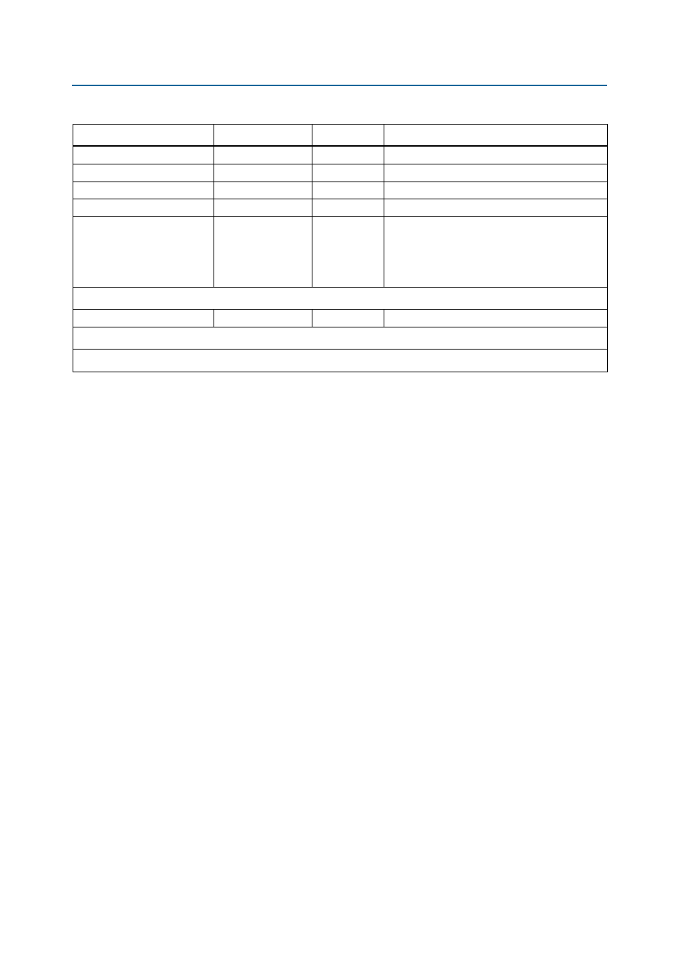
GXB2 Short Transmit Channel
Transceiver channel
2
Short transmit trace length (11.3G)
GXB2 Short Receive Channel
Transceiver channel
2
Short receive trace length (11.3G)
GXB2 Long Transmit Channel
Transceiver channel
2
15 inches trace length (11.3G)
GXB2 Long Receive Channel
Transceiver channel
2
5 inches trace length (11.3G)
GXB1 Four Full-Duplex
Transceiver Channels
(One entire block, excluding
two clock multiplier unit
(CMU) channels)
Transceiver channel
16
Four full-duplex channels from one entire
transceiver block (excluding two CMU channels)
Spares
Spare[7:0]
2.5-V CMOS inout
8
Spare signals to the MAX II CPLD
Total Device I/O: 220
Available Stratix IV GT I/O: 636
Table 2–4. Stratix IV GT I/O Usage Summary (Part 3 of 3)
Function
I/O Type
I/O Count
Description