Components and interfaces, Temperature measurement, Components and interfaces –20 – Altera Transceiver Signal Integrity Development Kit, Stratix IV GT Edition User Manual
Page 30: Temperature measurement –20
2–20
Chapter 2: Board Components
Components and Interfaces
Transceiver Signal Integrity Development Kit,
November 2011
Altera Corporation
Stratix IV GT Edition Reference Manual
lists the flash memory map storage for two FPGA bitstreams (factory and
user) as well as 40 MB of reserved user space for storage of PFL configuration settings,
software binaries, and other data relevant to the targeted FPGA design (Nios II
applications). For the EP4S100G2F40I1N FPGA device, each FPGA bitstream can be a
maximum of 94.54 Mb (less than 12 MB). Hence, the factory and user POF space is set
at 12 MB.
lists the flash memory device component reference and manufacturing
information.
Components and Interfaces
This section describes the temperature measurement and power measurement
circuitries and the board’s communication ports.
Temperature Measurement
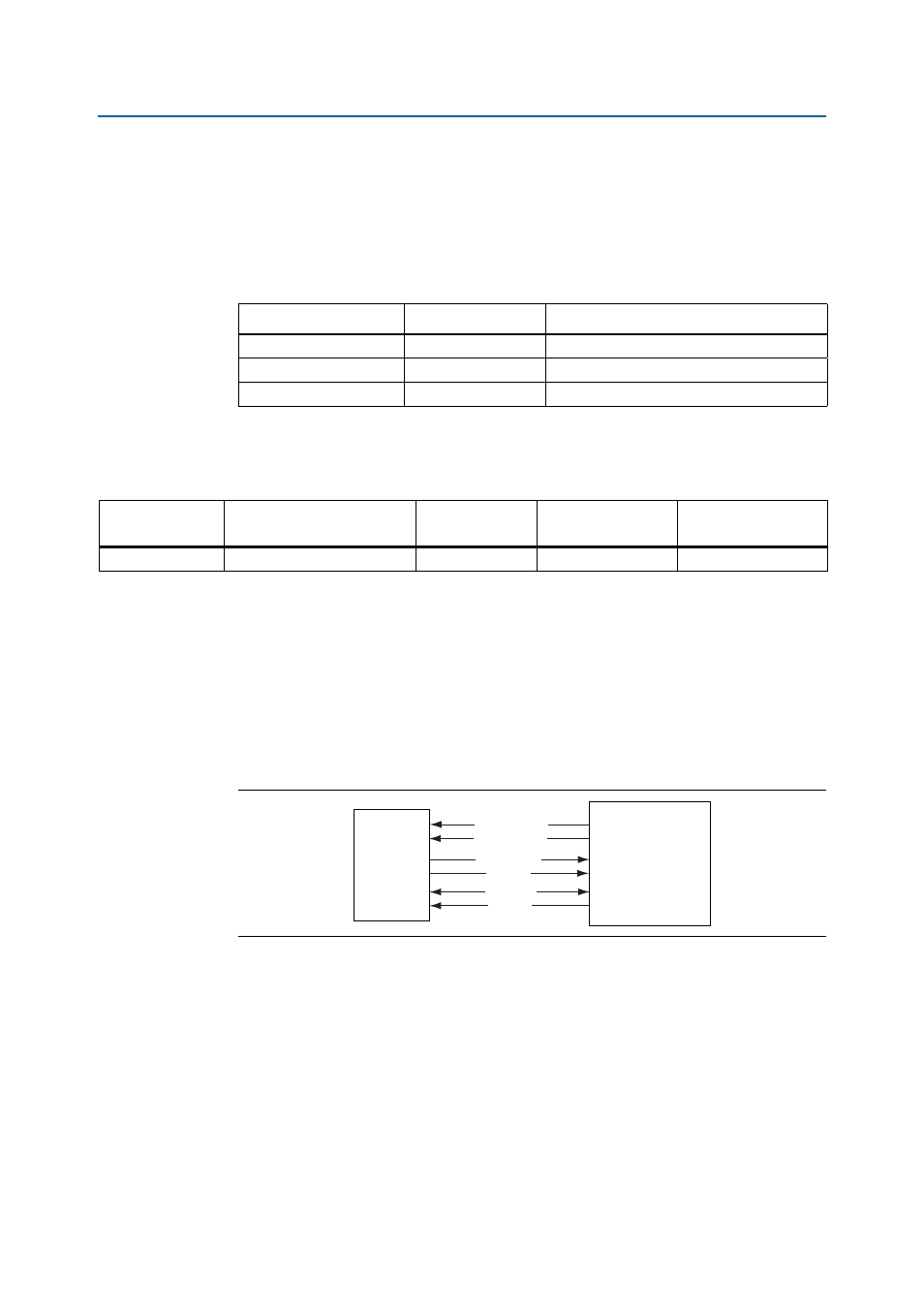
shows the block diagram for the temperature measurement circuitry.
Temperature monitoring for the Stratix IV die is achieved by using a MAX1619
temperature sense device. The MAX1619 connects to the FPGA by a 2-wire SMBus
interface. The OVERTEMPn and ALERTn signals from the MAX1619 connect to the FPGA
to allow it to immediately sense a temperature fault condition and turn on the
attached fan. The FPGA controls the fan based on the OVERTEMPn signal from the
MAX1619, or the fan can be set to always ON.
Table 2–17. Flash Memory Map
Name
Size (MB)
Address
Reserved
40
0x0180.0000 – 0x03FF.FFFF
USER
12
0x00C0.0000 – 0x017F.FFFF
FACTORY
12
0x0000.0000 – 0x00BF.FFFF
Table 2–18. Flash Memory Device
Board Reference
Description
Manufacturer
Manufacturing
Part Number
Manufacturer
Website
U39
512-Mb NOR-type flash
Numonyx
PC28F512P30BF
Figure 2–7. Temperature Measurement
Stratix IV GT
FPGA
(U33)
MAX1619
(U15)
TEMPDIODE_N
TEMPDIODE_P
ALERTn
OVERTEMPn
SMBCLK
SMBDATA