Altera Transceiver Signal Integrity Development Kit, Stratix IV GT Edition User Manual
Page 31
Chapter 2: Board Components
2–21
Components and Interfaces
November 2011
Altera Corporation
Transceiver Signal Integrity Development Kit,
Stratix IV GT Edition Reference Manual
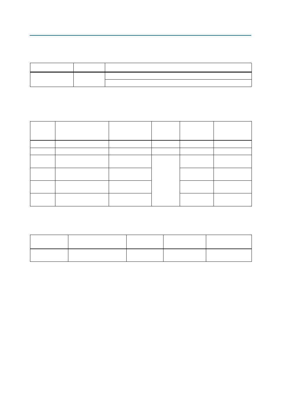
lists the fan control jumper (J64) which configures the fan.
An over-temperature orange warning LED (D6) also connects to the FPGA to indicate
that an over-temperature condition exists and that a fan should be attached and
running.
lists the pin-out of the temperature sense interface to the FPGA.
lists the temperature sensor component reference and manufacturing
information.
Table 2–19. Fan Control Jumper (J64)
Board Reference
Jumper Name
Description
J64
FAN
When jumper is installed on pins 1-2, the fan is auto-controlled by the FPGA.
When jumper is installed on pins 2-3, the fan is always on.
Table 2–20. Temperature Sensor Pin-Out
Board
Reference
Description
Schematic Signal
Name
I/O Standard
Stratix IV GT
Device Pin
Number
Other Connections
U15 pin 3
Analog sense DIODE P pin
TEMPDIODE_P
Analog
U33 pin A9
—
U15 pin 4
Analog sense DIODE N pin
TEMPDIODE_N
Analog
U33 pin E11
—
U15 pin 12
SMBus Data pin
S4_SMBDATA
2.5-V CMOS
U33 pin B14
10-k
Ω pull-up
resistor to 2.5 V
U15 pin 14
SMBus Clock pin
S4_SMBCLK
U33 pin A14
10-k
Ω pull-up
resistor to 2.5 V
U15 pin 9
Over Temperature signal
OVERTEMPn
U33 pin C14
10-k
Ω pull-up
resistor to 2.5 V
U15 pin 11
Alert signal
ALERTn
U33 pin D14
10-k
Ω pull-up
resistor to 2.5 V
Table 2–21. Temperature Sensor Component Reference
Board Reference
Description
Manufacturer
Manufacturing
Part Number
Manufacturer
Website
U15
Dual temperature sensor with
SMBus interface
Maxim Integrated
Products, Inc.
MAX1619MEE+T