Altera Active Serial Memory Interface User Manual
Page 19
• Read Memory Capacity ID from the EPCS/EPCQ/EPCQ-L Device
• Read Silicon ID from the EPCS Device
• Protect a Sector on the EPCS/EPCQ/EPCQ-L Device
• Read Data from the EPCS/EPCQ/EPCQ-L Device
• Fast Read Data from the EPCS/EPCQ/EPCQ-L Device
• Write Data to the EPCS/EPCQ/EPCQ-L Device
• Read Status Register of the EPCS/EPCQ/EPCQ-L Device
• Erase Memory in a Specified Sector on the EPCS/EPCQ/EPCQ-L256 Device
• Erase Memory in Bulk on the EPCS/EPCQ Device
• Erase Memory in Specified Die on EPCQ-L512 and EPCQ-L1024
• Enable 4-byte Addressing Operation for an EPCQ256/EPCQ-L256 or larger devices
• 4-byte Addressing Exit Operation for an EPCQ256/EPCQ-L256 or larger devices
Note: The timing diagrams show the expected results in the hardware and are not the actual results from
the simulation.
The general timing requirement for all operations is the
clkin
signal must toggle at the appropriate
frequency range at all times. The IP core uses the
clkin
signal to feed the EPCS/EPCQ/EPCQ-L device
and to perform internal processing. For a read operation, the
clkin
signal can toggle at a maximum
frequency of 20 MHz. For a fast read operation, the
clkin
signal can toggle at a maximum frequency of
25 MHz.
Note: Altera recommends that you check the
busy
signal before sending a new command. When the
busy
signal is deasserted, allow two clock cycles before sending a new signal. This delay allows the
circuit to reset itself before executing the next command.
Read Memory Capacity ID from the EPCS/EPCQ/EPCQ-L Device
Use the
read_rdid
signal to instruct the IP core to read the memory capacity ID from the EPCS/EPCQ/
EPCQ-L device.
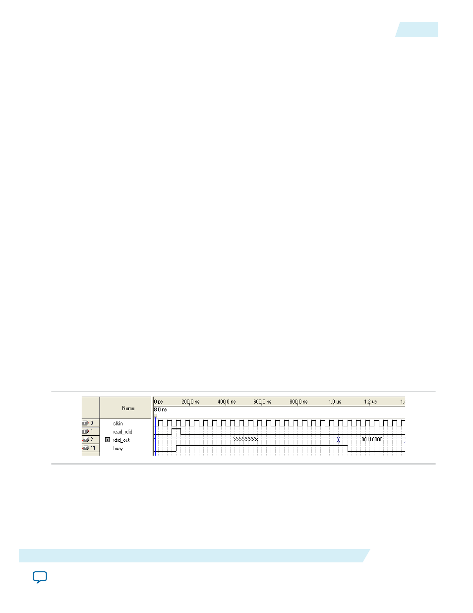
Figure 3: Reading Memory Capacity ID
This figure shows an example of the latency when the Altera ASMI Parallel IP core is executing the read
command. The latency shown does not correctly indicate the true processing time. The latency only
shows the command.
The IP core registers the
read_rdid
signal on the rising edge of the
clkin
signal. After the IP core
registers the
read_rdid
signal, the IP core asserts the
busy
signal to indicate that the read
command is in progress.
Ensure that the memory capacity ID appears on the
rdid_out[7..0]
signal before the
busy
signal is deasserted. This allows you to sample the
rdid_out[7..0]
signal as soon as the
busy
signal is deasserted.
UG-ALT1005
2014.12.15
Read Memory Capacity ID from the EPCS/EPCQ/EPCQ-L Device
19
Altera ASMI Parallel IP Core User Guide
Altera Corporation