1 adc raw value and initialisation value, 2 hardware calibration, Adc raw value and initialisation value – Pilz PSSu E S 2AI U User Manual
Page 16: Hardware calibration
Function description
Operating Manual PSSu E S 2AI U(T)
21405EN03
16
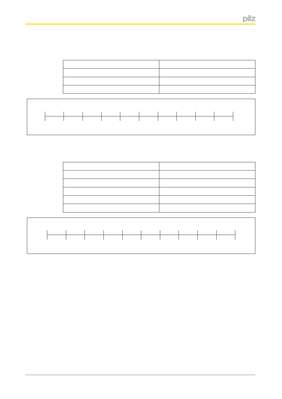
Analogue value and typical digital value with a voltage range of 0 ... +10 V plus de
fault values:
Analogue value of voltage
Decimal digital value
0 V
0
5 V
16 384
10 V
32 767
5 V
6 V
7 V
8 V
9 V
4 V
3 V
2 V
1 V
0 V
10 V
32 767
29 490
26 214
22 937
19 660
16 384
13 107
9 830
6 553
3 277
0
Analogue value and typical digital value with a voltage range of 10 V ... +10 V plus
default values:
Analogue value of voltage
Decimal digital value
10 V
32 767
5 V
16 384
0 V
0
5 V
16 384
10 V
32 767
0 V
2 V
4 V
6 V
8 V
-2 V
-4 V
-6 V
-8 V
-10 V
10 V
32 767
26 214
19 660
13 107
6 553
0
-6 553
-13 107
-19 660
-26 214
-32 767
4.2.3.1
ADC raw value and initialisation value
You can configure each channel so that the raw value from the AD converter is issued dir
ectly, without calibration or scaling.
If the AD converter fails to supply a valid value, the module will adopt the ADC initialisation
value for this channel instead. The default value is 4096
D
(1000
H
).
4.2.3.2
Hardware calibration
Each channel is calibrated exworks in order to correct component dispersion and other in
fluences.
The range is divided so that zero is assigned the value 0 and the end point is assigned the
value 4095
D
(0FFF
H
).