Pilz PNOZ mc6p CANopen coated version User Manual
Page 2
- 2 -
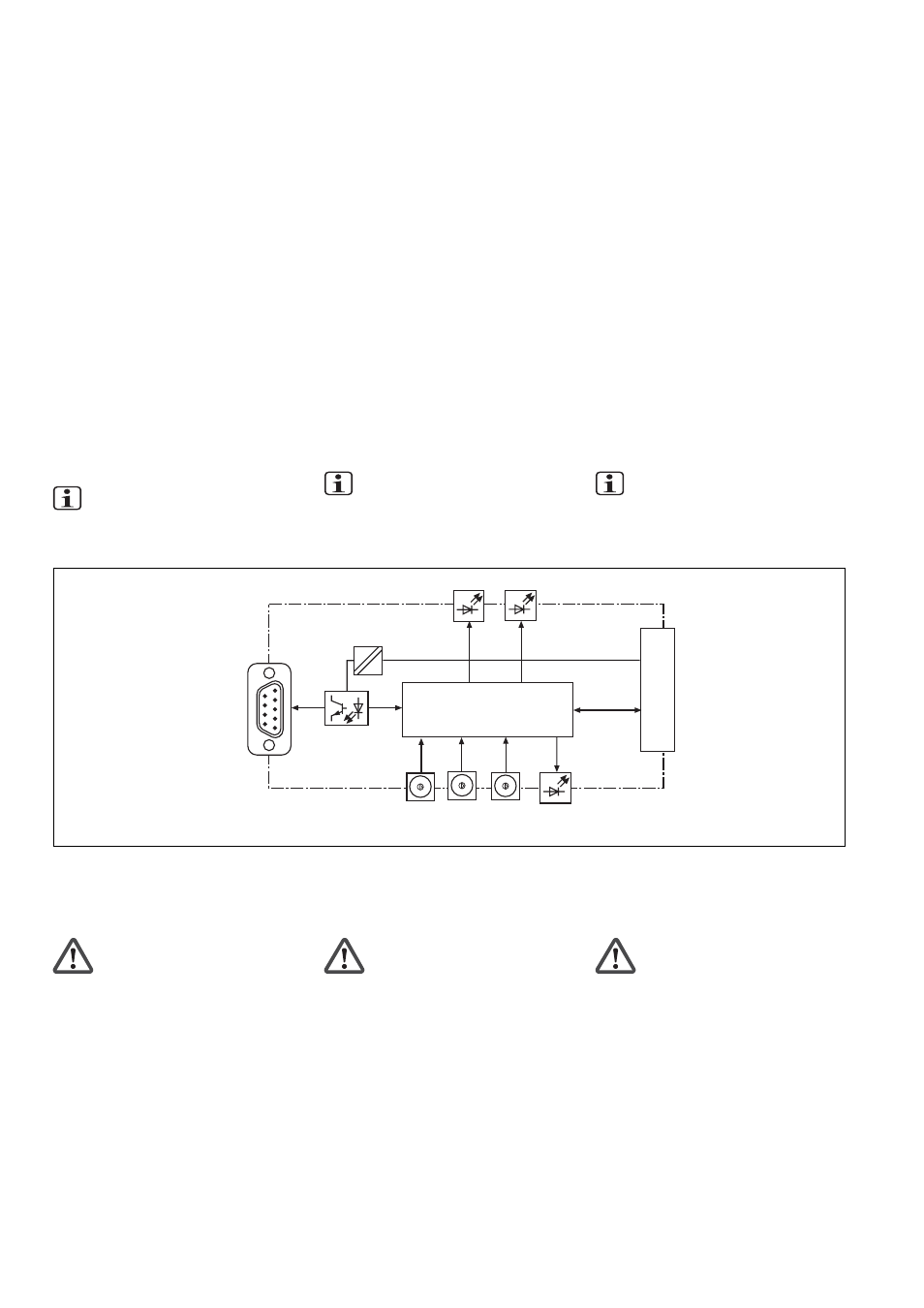
Innenschaltbild
PNOZ m1p
CANopen
x1
Controller
1234
9
8
7
6
0
5
x10
DC
DC
RUN
ERR
PWR
1234
9
8
7
6
0
5
1234
9
8
7
6
0
5
DR
Internal wiring diagram
Schéma interne
Modulmerkmale:
• konfigurierbar mit PNOZmulti
Configurator
• Stationsadressen wählbar von 1 ... 99 mit
Drehschaltern
• Statusanzeigen für Kommunikation mit
CANopen und von Fehlern
PNOZ mc6p (coated version) montie-
ren
Beachten Sie bei der Montage:
Achtung! Durch elektrostatische
Entladung können Bauteile der
Sicherheitssteuerung beschädigt
werden. Sorgen Sie für Entladung,
bevor Sie die Sicherheitssteuerung
berühren, z. B. durch Berühren einer
geerdeten, leitfähigen Fläche oder
durch Tragen eines geerdeten
Armbands.
• Montieren Sie das Sicherheitssystem in
einen Schaltschrank mit einer Schutzart
von mindestens IP54.
• Montieren Sie das Sicherheitssystem auf
eine waagrechte Tragschiene. Die
Lüftungsschlitze müssen nach oben und
unten zeigen (siehe Betriebsanleitung des
Basisgeräts PNOZ m0p, PNOZ m1p).
Andere Einbaulagen können zur Zerstö-
rung des Sicherheitssystems führen.
Module features:
• Can be configured using the PNOZmulti
Configurator
• Station addresses from 1 ... 99, selected
via rotary switches
• Status indicators for communication with
CANopen and for errors
Installing the PNOZ mc6p (coated
version)
Please note for installation:
Caution! Electrostatic discharge can
damage components on the safety
system. Ensure discharge before
touching the safety system, e.g. by
touching an earthed, conductive
surface or by wearing an earthed
armband.
• The safety system should be installed in a
control cabinet with a protection type of at
least IP54.
• Fit the safety system to a horizontal DIN
rail. The venting slots must point up and
down (see operating instructions for the
PNOZ m0p and PNOZ m1p base units).
Other mounting positions could damage
the safety system.
Caractéristiques du module :
• Paramétrable avec PNOZmulti Configurator
• Adresses des stations sélectionnables de
1 ... 99 par commutateurs rotatifs
• Affichage d’état pour la communication avec
le bus CANopen et pour les erreurs
Installer PNOZ mc6p (coated version)
Pour le montage, respectez les consignes
suivantes :
Attention ! Une décharge électros-
tatique peut endommager les
éléments de l’automate de sécurité.
Veillez à vous décharger avant de
toucher l’automate de sécurité, par
ex. en touchant une surface
conductrice mise à la terre ou en
portant un bracelet de mise à la
terre.
• Montez le système de sécurité dans une
armoire d’indice de protection IP 54 au
moins.
• Montez le système de sécurité sur un
profilé support horizontal. Les ouïes de
ventilation doivent être orientées vers le
haut et vers le bas (voir le manuel d’utili-
sation de l’appareil de base PNOZ m0p,
PNOZ m1p). D’autres positions de
montage peuvent entraîner la destruction
du système de sécurité.
Funktionsbeschreibung
Arbeitsweise:
Die über den CANopen zu übertragenden
Daten werden im PNOZmulti Configurator
ausgewählt und konfiguriert.
Die Verbindung zwischen Basisgerät und
Erweiterungsmodul erfolgt über eine
Steckbrücke. Über diese Steckbrücke wird
das Erweiterungsmodul auch mit Spannung
versorgt. Die Stationsadresse und die
Übertragungsrate werden mit Drehschaltern
eingestellt. Nach Einschalten der
Versorgungsspannung oder einem Reset
des Sicherheitssystems PNOZmulti wird
das Erweiterungsmodul automatisch
konfiguriert und gestartet.
Funktionen:
LEDs zeigen den Status des Erweiterungs-
moduls am CANopen an.
INFO
In der Online-Hilfe des PNOZmulti
Configurators ist die Konfiguration des
Erweiterungsmoduls ausführlich
beschrieben.
Function description
Operation:
The data to be transferred via CANopen are
selected and configured in the PNOZmulti
Configurator.
The base unit and the expansion module are
connected via a jumper. The expansion
module is also supplied with voltage via this
jumper. The station address and the
transmission rate are set using rotary
switches. After the supply voltage is
switched on or the PNOZmulti safety system
is reset, the expansion module is configured
and started automatically.
Functions:
LEDs indicate the status of the expansion
module on CANopen.
INFORMATION
The configuration of the expansion
module is described in detail in the
PNOZmulti Configurator’s online help.
Descriptif du fonctionnement
Mode de travail :
Les données à transmettre par CANopen
sont sélectionnées et configurées dans le
Configurateur PNOZmulti.
Le raccordement entre l’appareil de base et
le module d’extension est réalisé au moyen
d’un pont enfichable. Celui-ci assure
également l’alimentation du module
d’extension. L’adresse station et la vitesse de
transmission sont réglées au moyen de
commutateurs rotatifs. Après application de
la tension d’alimentation ou réinitialisation du
système de sécurité PNOZmulti, le module
PNOZ mc6p est automatiquement configuré
et démarré.
Fonctions :
Les LED affichent l’état du module
d’extension sur le CANopen.
INFORMATION
La configuration du module
d’extension est décrite en détail dans
l’aide en ligne du Configurateur
PNOZmulti.