5 installation, General installation guidelines, 1 dimensions – Pilz PNOZ mmc6p CAN User Manual
Page 17: 5installation, 1 general installation guidelines
Pilz GmbH & Co. KG, Felix-Wankel-Straße 2, 73760 Ostfildern, Germany
Telephone: +49 711 3409-0, Telefax: +49 711 3409-133, E-Mail: [email protected]
5-1
5.1
General installation guidelines
5
Installation
5
5000
Installation
Installation
5-
5.1
General installation guidelines
5100
General installation guidelines
5-
Montage_multi_mini_allgemein
The unit should be installed in a control cabinet with a protection type
of at least IP54.
Fit the safety system to a horizontal mounting rail. The venting slots
must face upwards and downwards. Other mounting positions could
destroy the safety system.
Use the notch on the rear of the unit to attach it to a mounting rail.
In environments exposed to heavy vibration, the unit should be se-
cured using a fixing element (e.g. retaining bracket or end angle).
Push the unit upwards or downwards before lifting it from the mount-
ing rail.
To comply with EMC requirements, the mounting rail must have a low
impedance connection to the control cabinet housing.
Montage_multi_mini_Temperatur
The ambient temperature of the PNOZmulti units in the control cabi-
net must not exceed the figure stated in the technical details, other-
wise air conditioning will be required.
Montage_EMV ESD
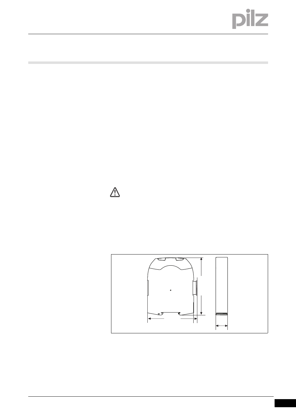
5.1.1
Dimensions
Dimensions
5-
Abmessungen_multi_mini_Feldbus
CAUTION!
Damage due to electrostatic discharge!
Electrostatic discharge can damage components. Ensure
against discharge before touching the product, e.g. by touching
an earthed, conductive surface or by wearing an earthed arm-
band.
100 (3,94")
22,5
(0.88")
114,72 (4,52")