1 field wiring, Installation instructions – Spectrum Controls 140 ACI 052 00sc User Manual
Page 45
Before installing the module, you should:
Configure all of the appropriate zoom screen, configuration and other
necessary set up according to Chapter 2.
Field wire the modules terminal block for your application.
For field wiring, use shielded, twisted-pair cable (such as Belden 9418 for
voltage and current applications), and ground each cables shield wire at one
end only. At the opposite end of each cable, tape the exposed shield wire
to insulate it from electrical contact. A good shield wire ground is a rack
assembly mounting bolt or stud.
5.1
Field Wiring
☞ Note: In the process of wiring the modules, route all signal wires as far as possible from potential
sources of electrical noise, such as motors, transformers, etc., (especially ac devices).
As a general rule, allow 15.2 cm (6 in) of separation for every 120V of power. Signal
wires must never share the same conduit with ac wiring. Also, when you must route
signal wires past ac wiring, do so at right angles.
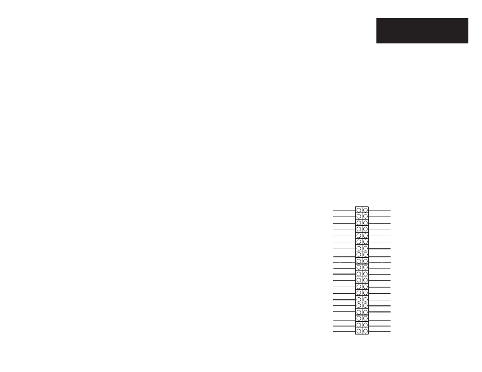
Single Ended Field Wiring
140 ACI 052 00sc Wiring Diagram
39
Installation Instructions
32-Channel Analog Input Module
Quantum 140 ACI 052 00sc
(IN+)11
(IN+)3
(IN+)1
COM GROUP 1
(IN+)6
(IN+)9
(IN+)8
(IN+)27
(IN+)19
(IN+)17
COM GROUP 3
(IN+)22
(IN+)25
(IN+)24
(IN+)32
(IN+)30
COM GROUP 4
(IN+)16
(IN+)14
COM GROUP 2
COM GROUP 4
(IN+)31
(IN+)29
COM GROUP 2
(IN+)15
(IN+)13
(IN+)28
(IN+)20
(IN+)18
(IN+)21
(IN+)23
(IN+)26
COM GROUP 3
(IN+)12
(IN+)4
(IN+)2
(IN+)5
(IN+)7
(IN+)10
COM GROUP 1
7
1
6
1
3
5
9
1
1
1
3
1
5
1
7
1
9
2
1
2
3
2
5
2
7
2
9
3
1
3
3
3
5
3
7
3
9
2
4
6
8
1
0
1
2
1
4
1
8
2
0
2
2
2
4
2
6
2
8
3
0
3
2
3
4
3
6
3
8
4
0