Spectrum Controls 1746sc-NI8u User Manual
Page 95
Appendix A: Module Specifications
83
The following table provides the maximum error for each RTD and
resistance type when the 10 Hz, 50 Hz, and 60 Hz filters are used and the
module is operating at 0°C to 60°C and was at that temperature. Errors
due to lead wire resistance mismatches are not included.
Input
Max. Error
Type
0°C to 60°C
100
Ω
Pt 385
±3.3°C
200
Ω
Pt 385
±2.8°C
500
Ω
Pt 385
±3.0°C
1000
Ω
Pt 385
±2.9°C
100
Ω
Pt 3916
±2.7°C
200
Ω
Pt 3916
±2.4°C
500
Ω
Pt 3916
±2.3°C
1000
Ω
Pt 3916
±2.2°C
10
Ω
Cu 426
±4.5°C
120
Ω
Ni 618
±0.8°C
120
Ω
Ni 672
±0.8°C
3000
Ω
Resistance
±7.0
Ω
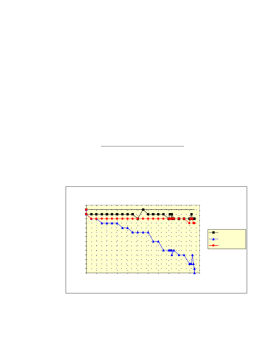
The diagrams that follow provide data from a sample module for a given
RTD type over a range of inputs, over temperature.
100
Ω
Pt 385 RTD, Example Deviations
-1.4
-1.3
-1.2
-1.1
-1
-0.9
-0.8
-0.7
-0.6
-0.5
-0.4
-0.3
-0.2
-0.1
0
0.1
-200 -100
0
100
200
300
400
500
600
700
800
900
Degrees C RTD Input
Degrees C Deviation
Ch 7 Delta, 25C
Ch 7 Delta, 0C
Ch 7 Delta, 60C