Current input, Non-current input, Jp11 setup – Spectrum Controls 1746sc-NI8u User Manual
Page 23: Shunt in place, Shunt removed
Chapter 2: Installing And Wiring Your Module
11
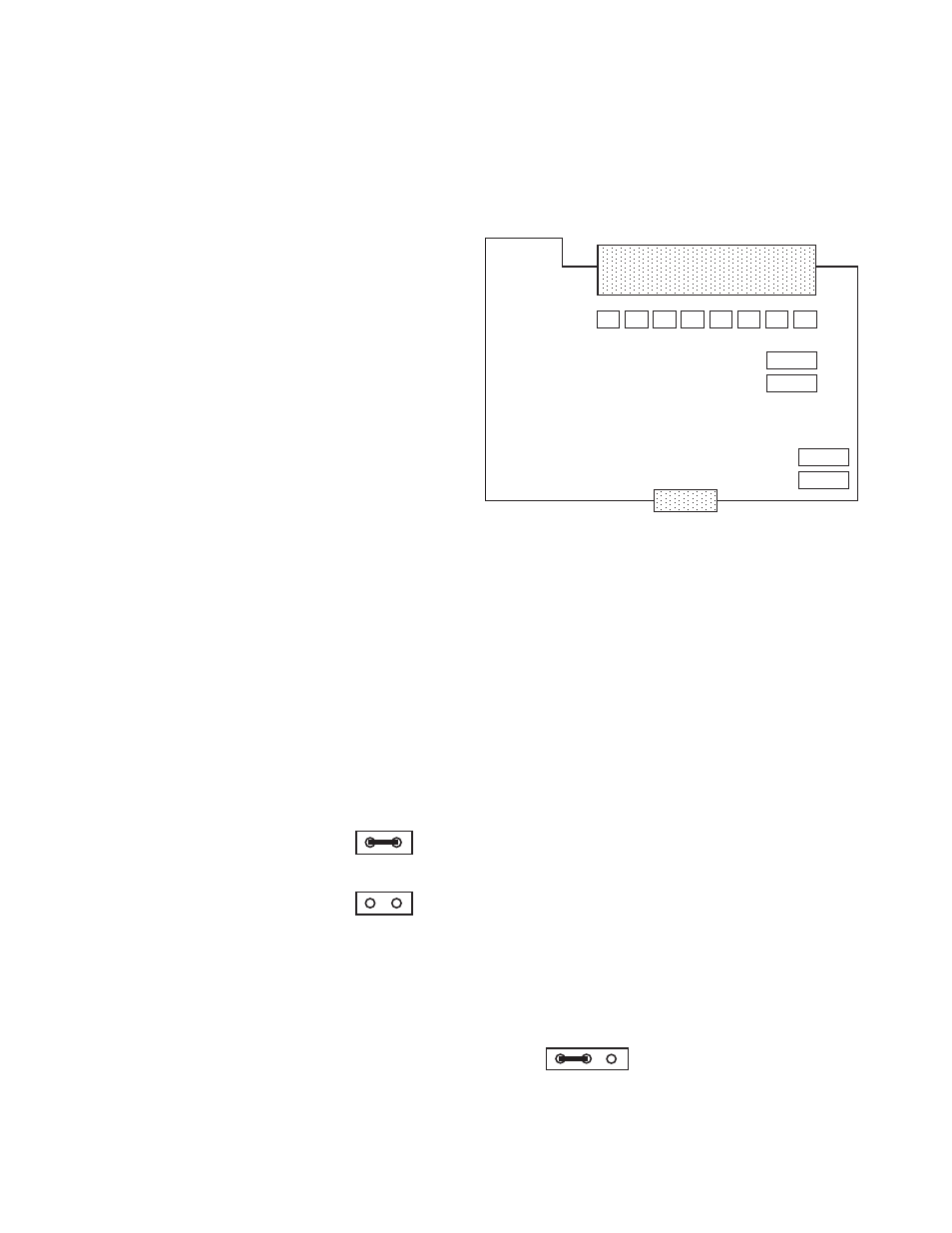
The following diagram shows the module outline defining the placement of
the various shunts, looking at the primary side of the board, with the
terminal block pointing up. A brief description of each follows.
Terminal Block Header
JP1
JP2
JP3
JP4
JP5
JP6
JP7
JP8
JP11
JP12
JP9
JP10
JP1, JP2, JP3, JP4,
JP5, JP6, JP7, and
JP8 Setup
There are eight shunts corresponding to eight inputs, respectively,
that exist to support the 0 to 20mA or 4 to 20mA current input
selections. JP1 corresponds to channel 0, and JP8 corresponds to
channel 7. The shunts of JP2 through JP7 follow for channels 1
through 6, respectively. These shunts are two pin headers that only
need to be connected if a channel is to be configured for current
input. If the channel is to be used for any other type (thermocouple,
millivolt, voltage for channels 0 through 3, or thermocouple,
millivolt, voltage, RTD, or resistance for channels 4 through 7), then
the pins are to be left open and unconnected.
Current Input
Shunt in place
Non-Current Input
Shunt removed
JP11 Setup
Located in the bottom right hand corner, JP11 should always have
pins 1 and 2 connected as shown. This shunt is used during
manufacturing of the module, and should never be moved by the
user.
JP11