Spectrum Controls 1746sc-NI8u User Manual
Page 27
Chapter 2: Installing And Wiring Your Module
15
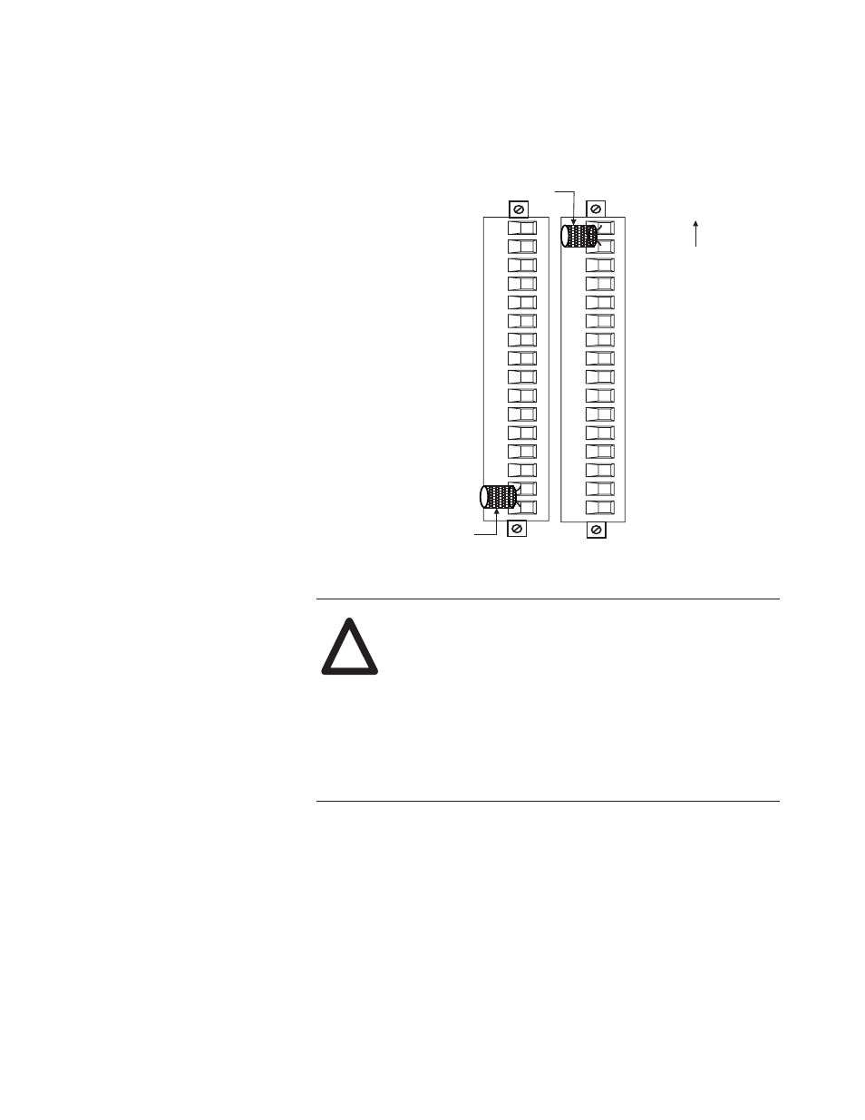
Figure 2.2.
Terminal block diagram with CJC
sensors
CJC Sensors
TB1
CJC Sensors
CH0+
CH0-
Shield 0/1
CH1+
CH1-
EXC4+
CH4+
CH4-
EXC4-
Shield 4/5
EXC5+
CH5+
CH5-
CJCB-
EXC5-
CJCB+
CJCA+
CJCA-
CH2+
CH2-
SHIELD 2/3
CH3+
CH3-
EXC6+
CH6+
CH6-
EXC6-
SHIELD 6/7
EXC7+
EXC7-
CH7+
CH7-
TB2
LEDS
CAUTION
POSSIBLE EQUIPMENT OPERATION
Before wiring your module, always disconnect power
from the SLC 500 system and from any other source to
the module.
Failure to observe this precaution can cause unintended
equipment operation and damage.
Wiring Your Module
Follow these guidelines to wire your input signal cables:
• Power, input, and output (I/O) wiring must be in accordance with
Class 1, Division 2 wiring methods [Article 501-4(b) of the
National Electrical Code, NFPA 70] and in accordance with the
authority having jurisdiction.
• Peripheral equipment must be suitable for the location in which it
is used.
• Route the field wiring away from any other wiring and as far as
possible from sources of electrical noise, such as motors,
!