Spectrum Controls 1746sc-NI8u User Manual
Page 32
20
SLC 500
™
Universal Analog Input Module
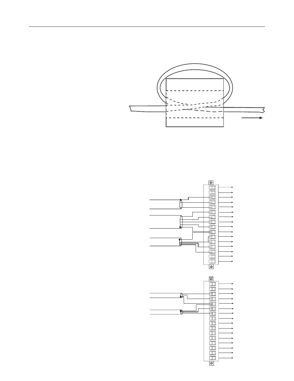
Figure 2.3
Ferrite EMI suppressor for CE
compliance
Module
Note: Please refer to Appendix C for additional information on
wiring and using grounded junction, ungrounded junction and
exposed juction thermocouple types.
Figure 2.4
Terminal block diagram with input
cable
CH0+
CH0-
Shield for CH0 and CH1
CH1+
CH1-
EXC4+
CH4+
CH4-
EXC4-
Shield for CH4 and CH5
EXC5+
CH5+
CH5-
EXC5-
CJCB+
CJCB-
TB1
4-WIRE RTD CABLE
3-WIRE RTD CABLE
THERMOCOUPLE, mA,
mV or V CABLE
CJC A+
CJC A -
CH2+
CH2-
Shield for CH2 and CH3
CH3+
CH3-
EXC6+
CH6+
CH6-
EXC6-
Shield for CH6 and CH7
EXC7+
CH7+
CH7-
EXC7-
THERMOCOUPLE, mA,
mV or V CABLE
TB2
See also other documents in the category Spectrum Controls Measuring instruments:
- 1756sc-CTR8 (74 pages)
- 1756sc-HART Modules (170 pages)
- 1756sc-IF8u (118 pages)
- 1769sc-HART Modules (186 pages)
- 1769sc-HART Modules (176 pages)
- 1769sc-IF8u (126 pages)
- 1769sc-IT6I (82 pages)
- 1769sc-IR6I (74 pages)
- 2080sc-IF4u (12 pages)
- 2080sc-OW2IHC (10 pages)
- 2080sc-NTC (30 pages)
- 2080sc-BAC (56 pages)
- 1762sc-IF8U (12 pages)
- 1762sc-IF8U (38 pages)
- 1762sc-IF4OF4 (12 pages)
- 1762sc-IF4OF4 (42 pages)
- 1762sc-OF8 (12 pages)
- 1762sc-OF8 (42 pages)
- 1734sc-IE4CH (84 pages)
- 1734sc-IF4U (50 pages)
- 1734sc-OE2CIH (74 pages)
- 1794sc-IF8IU (3 pages)
- 1794sc-IF8IU (56 pages)
- 1794sc-IRT8I (3 pages)
- 1794sc-IRT8I (54 pages)
- 1746sc-CTR4 (66 pages)
- 1746sc-INI4vi (58 pages)
- 1746sc-INO4vi (48 pages)
- 1746sc-IA8i (27 pages)
- 1771sc-IFE32 (50 pages)
- 1771sc-IMI16 (8 pages)
- 140 MPM 204 00sc (66 pages)
- 140 EHC 208 00sc (81 pages)
- 140 AUI 040 00sc (52 pages)
- 140 ACI 051 00sc (57 pages)
- 140 ACI 052 00sc (62 pages)