Figure 3.1 image table – Spectrum Controls 1746sc-NI8u User Manual
Page 36
24
SLC 500
™
Universal Analog Input Module
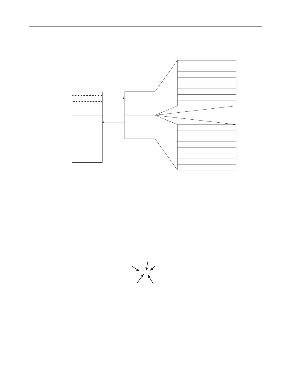
Figure 3.1
Image table
Input
Scan
Output Image
Slot e
Input Image
Slot e
SLC 5/0X
Data Files
Word 0
O:e.0
Word 1
O:e.1
Word 2
O:e.2
Word 3
O:e.3
Bit 15
Bit 0
Address
Channel 0 Configuration Word
Channel 1 Configuration Word
Channel 2 Configuration Word
Channel 3 Configuration Word
Word 4
O:e.4
Word 5
O:e.5
Word 6
O:e.6
Word 7
O:e.7
Channel 4 Configuration Word
Channel 5 Configuration Word
Channel 6 Configuration Word
Channel 7 Configuration Word
Output Image
8 Words
Thermocouple
Module
Image Table
Word 0
I:e.0
Word 1
I:e.1
Word 2
I:e.2
Word 3
I:e.3
Bit 15
Bit 0
Address
Channel 0 Data or Status Word
Channel 1 Data or Status Word
Channel 2 Data or Status Word
Channel 3 Data or Status Word
Word 4
I:e.4
Word 5
I:e.5
Word 6
I:e.6
Word 7
I:e.7
Channel 4 Data or Status Word
Channel 5 Data or Status Word
Channel 6 Data or Status Word
Channel 7 Data or Status Word
Input Image
8 Words
Output
Scan
Output Image - Configuration Words
Eight words of the SLC processor’s output image table are reserved
for the module. Output image words 0-7 are used to configure the
module’s input channels 0-7. Each output image word configures a
single channel, and can be referred to as a configuration word. Each
word has a unique address based on the slot number assigned to the
module.
Example Address - If you want to configure channel 2 on the
module located in slot 4 in the SLC chassis, your address would be
O:4.2.
O:4.2
File type
Slot
Word
Word
Delimiter
Element
Delimiter
Chapter 4, Channel Configuration, Data, and Status, gives you
detailed bit information about the data content of the configuration
word.