Channel configuration, data, and status, Chapter 4 – Spectrum Controls 1746sc-NI8u User Manual
Page 45
Chapter 4:
Channel Configuration, Data, and Status
33
Channel Configuration, Data,
and Status
Read this chapter to:
• configure each input channel
• check each input channel’s configuration and status
Channel
Configuration
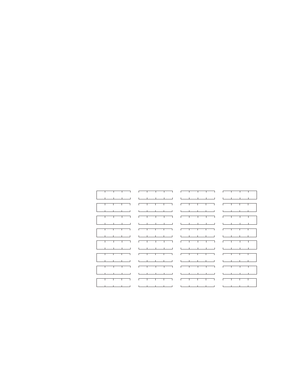
Channel configuration words appear in the SLC controller’s output image
table as shown below. Words 0-7 correspond to module channels 0-7.
After module installation, you must configure each channel to establish the
way the channel operates (e.g., input type, temperature units, etc.). You
configure the channel by setting bits in the configuration word using your
programmer. We present bit descriptions next.
15
SLC Output Image (Configuration) Words
O:e.2
O:e.3
O:e.4
O:e.5
O:e.6
O:e.7
Channel 0 Configuration Word
0
O:e.0
Channel 1 Configuration Word
O:e.1
Channel 2 Configuration Word
Channel 3 Configuration Word
Channel 4 Configuration Word
Channel 5 Configuration Word
Channel 6 Configuration Word
Channel 7 Configuration Word
e = slot number of the module
Chapter 4