Spectrum Controls 1746sc-NI8u User Manual
Page 41
Chapter 3: Things To Consider Before Using Your Module
29
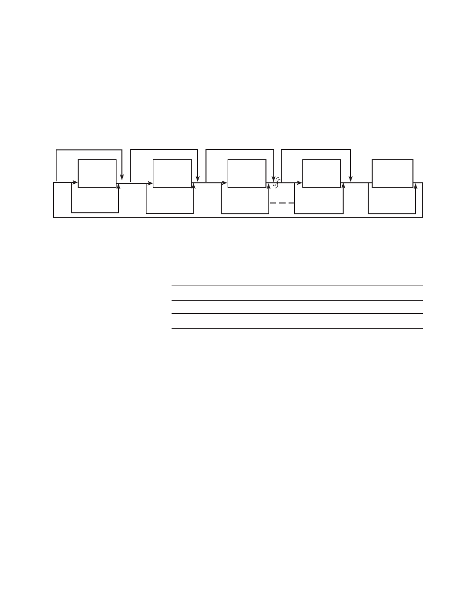
Update Time
The universal module update time is defined as the time required for the
module to sample and convert the input signals of all enabled input
channels and make the resulting data values available to the SLC
processor. It can be calculated by adding the sum of all enabled sample
times, plus one CJC update time or one lead resistance update time.
Channel 0 Disabled
Enabled
Channel 1 Disabled
Channel 2 Disabled
Enabled
Channel 7 Disabled
Enabled
Sample
Channel 0
Update CJC
Sample
Channel 1
Calculate
Previous
Sample
Channel 2
Calculate
Previous
Sample
Channel 7
Calculate
Previous
Sample CJC or
Lead Resistance
Calculate
Previous
Enabled
The following table shows the channel sampling time for each filter
frequency.
Table 3.2 Channel Sampling Time
Channel Sampling Time for Each Filter Frequency (all values ±1 msec)
Channel Sampling Time
250 Hz Filter
60 Hz Filter
50 Hz Filter
10 Hz Filter
26 msec
64 msec
74 msec
314 msec
The times above include a settling time necessary between input channel
readings.
In addition, on each module scan the module will sample either one CJC
input or one lead resistance input if any enabled channel input type is a
thermocouple, RTD, or resistance input. The CJC sampling time is 64
msec. The lead resistance sampling time is equal to the channel sampling
time for that RTD. When both thermocouple inputs and RTD or
resistance inputs are used, the module will alternate between sampling one
CJC and one lead resistance.
The fastest module update time occurs when only one millivolt channel
with a 250 Hz filter frequency is enabled.
Module update time = 26 msec
The slowest module update time occurs when eight channels, four
thermocouples and four RTDs, each using a 10 Hz filter frequency,
are enabled.
Module update time = 314 msec + 314 msec + 314 msec + 314 msec +
314 msec + 314 msec + 314 msec + 314 msec + 314 msec = 2.826 sec