Spectrum Controls 1746sc-NI8u User Manual
Page 80
68
SLC 500
™
Universal Analog Input Module
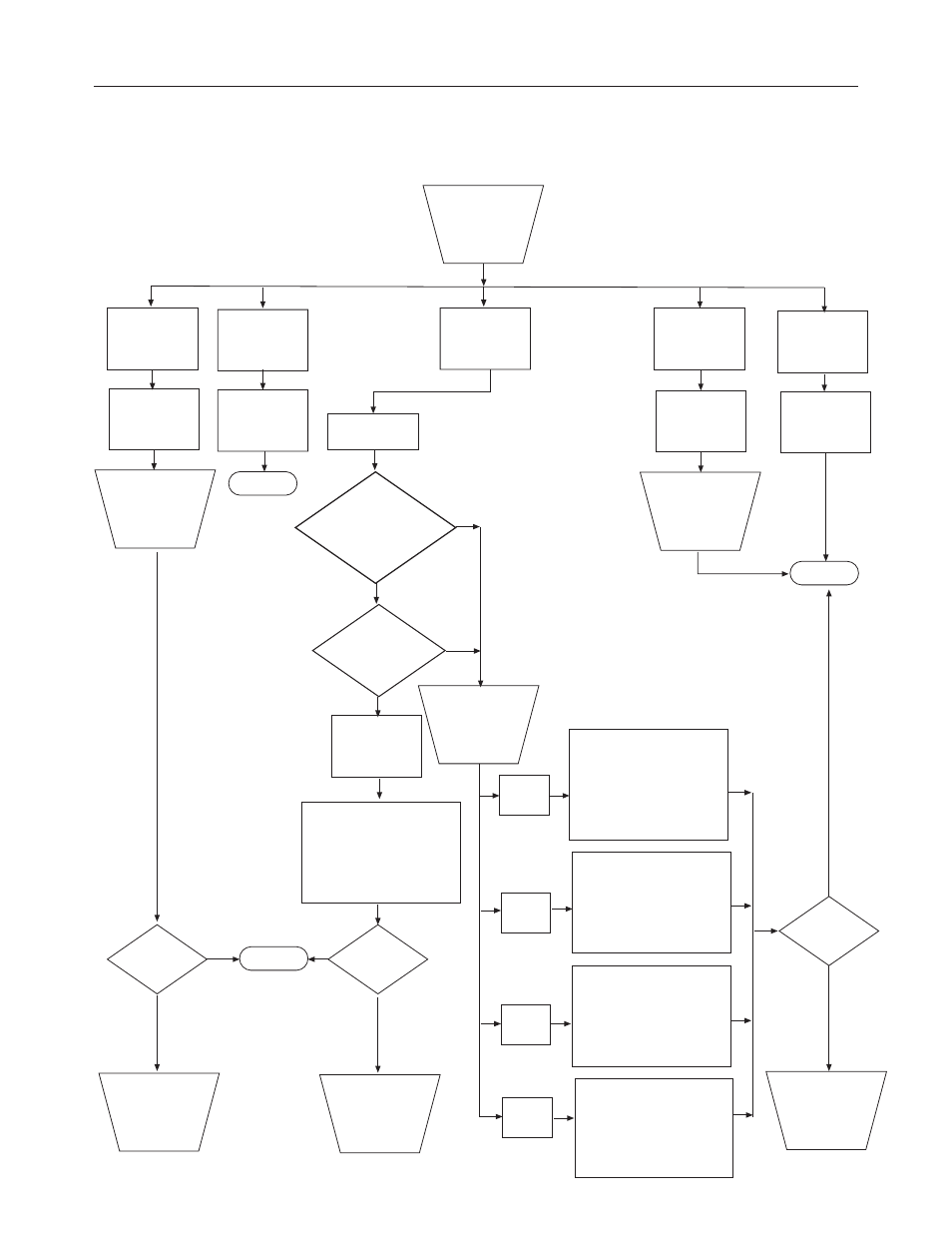
Figure 6.1 Troubleshooting Flowchart
Normal module
operation.
Module
Status LED(s)
off.
Module fault
condition.
Check to see
that module is
seated properly
in chassis.
Cycle power.
Is problem
corrected?
Contact you local
distributor or
Spectrum
Controls.
Yes
No
End
Module
Status LED
on.
Check LEDs
on module.
Channel
Status LED(s)
blinking.
Channel
Status LED(s)
off.
Channel
Status LED(s)
on.
Channel is
not enabled.
Channel is
enabled and
working.
Enable channel if
desired by setting
channel config.
word (bit 0 = 1).
Retry.
End
Fault
condition.
Check channel
status word
bits 1215.
Bit 15
set (1)
Yes
End
Are
faulted channel(s)
configured for mV or
thermocouple
input?
Is more than one
LED blinking?
CJC fault
has probably
occurred
mV, mA,
RTD or resistance
No
Yes
Check that wiring is secure
at both CJCs and that the
temperature within the
enclosure is in the range
limits of the CJC sensor.
(Refer to Chapter One.)
Is problem
corrected?
Contact you local
distributor or
Spectrum
Controls.
No
Channel error. Check
configuration word
for a valid input type
configuration and insure
bit 14 is set to zero.
Retry.
Over-range condition exists.
The input signal is greater
than the high scale limit for
the channel or the CJC
connections. Correct and
Retry.
Bit 14
set (1)
Under-range condition exists.
The input signal is less than
the low scale limit for the
channel or the CJC
connections. Correct and
Retry.
Bit 13
set (1)
An open-circuit condition is
present. Check channel and
CJC wiring for open or
loose connections. Check
for short circuited RTD
connections. Retry.
Bit 12
set (1)
Contact you local
distributor or
Spectrum
Controls.
No
Yes
Is problem
corrected?
Thermocouple