Spectrum Controls 1746sc-NI8u User Manual
Page 29
Chapter 2: Installing And Wiring Your Module
17
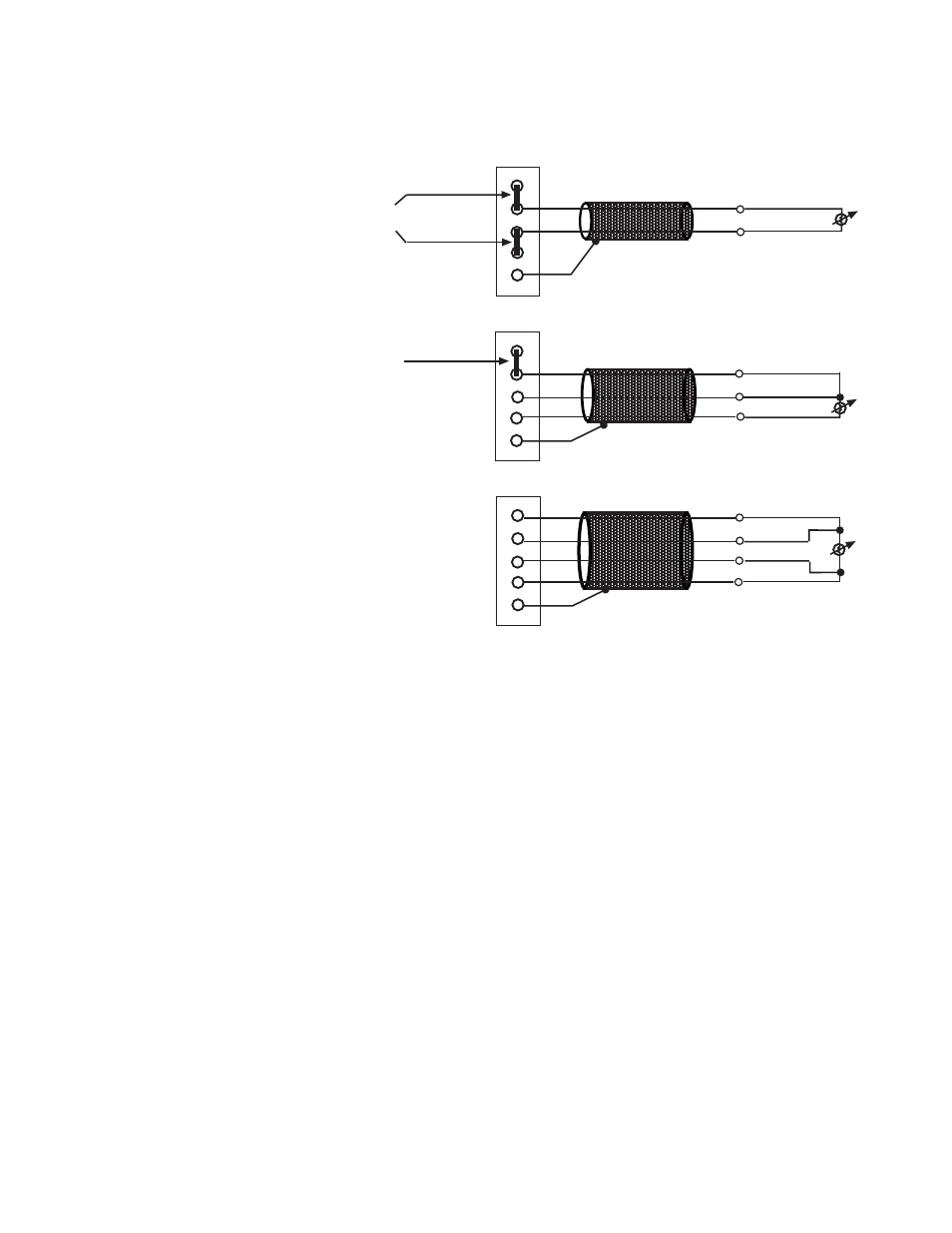
2-Wire RTD Interconnection
EXC4+
CH4+
CH4-
EXC4-
Shield 4/5
EXC4+
CH4+
CH4-
EXC4-
Shield 4/5
3-Wire RTD Interconnection
EXC4+
CH4+
CH4-
EXC4-
Shield 4/5
4-Wire RTD Interconnection
RTD
RETURN
ADD
JUMPER
CABLE SHIELD
ADD
JUMPER
RTD
CABLE SHIELD
CABLE SHIELD
SENSE
RETURN
RETURN
SENSE POS
SENSE NEG
RTD
These are:
* 2-wire RTDs, which are composed of 2 RTD lead wires (RTD and
Return)
* 3-wire RTDs, which are composed of a Sense and 2 RTD lead wires
(RTD and Return)
* 4-wire RTDs, which are composed of 2 Sense and 2 RTD lead wires
(RTD and Return).
In any RTD sensing system, it is important that the lead and sense wire
resistances are matched as much as possible. The lead lengths, and their
resulting impedances, must be matched and kept small to eliminate the
introduction of connectivity errors. The 4-wire RTDs are the most
accurate, with 2-wire RTDs being the most inaccurate. In 2-wire the lead
resistance adds error to the resulting degree reading. With a 200µA
current source, 1
Ω
of lead resistance adds 200µV, or 3.45°C error, with
the 100
Ω
385 alpha type. To gain an understanding of how lead
resistance affects RTD readings, the µV/C for each RTD type is listed
below. The current source is 200µA.