Install components to pc board, Continue, Start here continue start here – Elenco Deluxe Digital / Analog Trainer with Tools Kit Version User Manual
Page 9
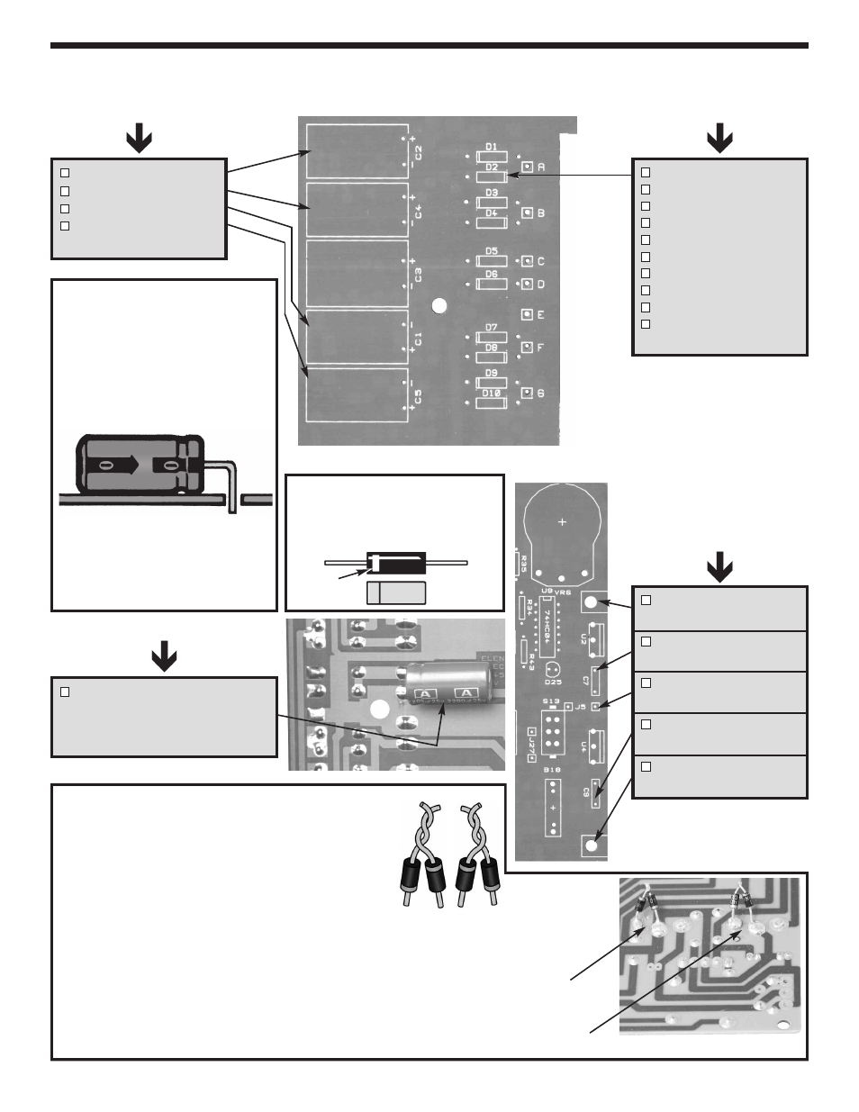
Figure K
Diodes have polarity. Mount them
with the band as shown on the
top legend.
Figure J
These lytics must be mounted
horizontal to the PC board. Bend
the leads at right angles and then
insert the leads into the PC board
with the negative (–) lead and the
positive (+) lead in the correct
holes as marked on the PC board.
Warning: If the capacitor is
connected with incorrect polarity,
it may heat up and either leak or
cause the capacitor to explode.
-8-
INSTALL COMPONENTS TO PC BOARD
C2 - 1,000
m
F 35V lytic
C4 - 1,000
m
F 35V lytic
C1 - 1,000
m
F 35V lytic
C5 - 1,000
m
F 35V lytic
(see Figure J)
Continue
L-bracket
(see Figure B)
C7 - .1
m
F mylar (104)
(see Figure D)
J5 - Jumper wire *
(see Figure F)
C9 - .1
m
F (104) mylar
(see Figure D)
L-bracket
(see Figure B)
D1 - 1N4001 diode
D2 - 1N4001 diode
D3 - 1N4001 diode
D4 - 1N4001 diode
D5 - 1N4001 diode
D6 - 1N4001 diode
D7 - 1N4001 diode
D8 - 1N4001 diode
D9 - 1N4001 diode
D10 - 1N4001 diode
(see Figure K)
Bottom right corner of PC board
C3 - 2200
m
F lytic
Mount on foil side of PC board
Note the polarity
(see Figure J)
Top right corner of PC board
* Leftover wire will be used
in future sections.
Band
+–
Start Here
Continue
Start Here
You need to install four diodes on the solder side of
the PC board for VR1 and VR2.
VR1 & VR2
1. Connect the anode side of one diode to the
cathode side of another by twisting the leads
together as shown in Figure L.
2. Cut the untwisted lead to 1/4” length (see Figure L).
3. Tack solder the diodes across the left lead and the
center hole of VR1 & VR2 as shown in Figure M.
Make sure the diodes are facing in the correct
position.
4. Solder the twisted leads and then cut off the excess
leads.
Figure L
VR2
Note diode polarity.
VR1
Note diode polarity.
Figure M
VR1
VR2