Elenco Deluxe Digital / Analog Trainer with Tools Kit Version User Manual
Page 43
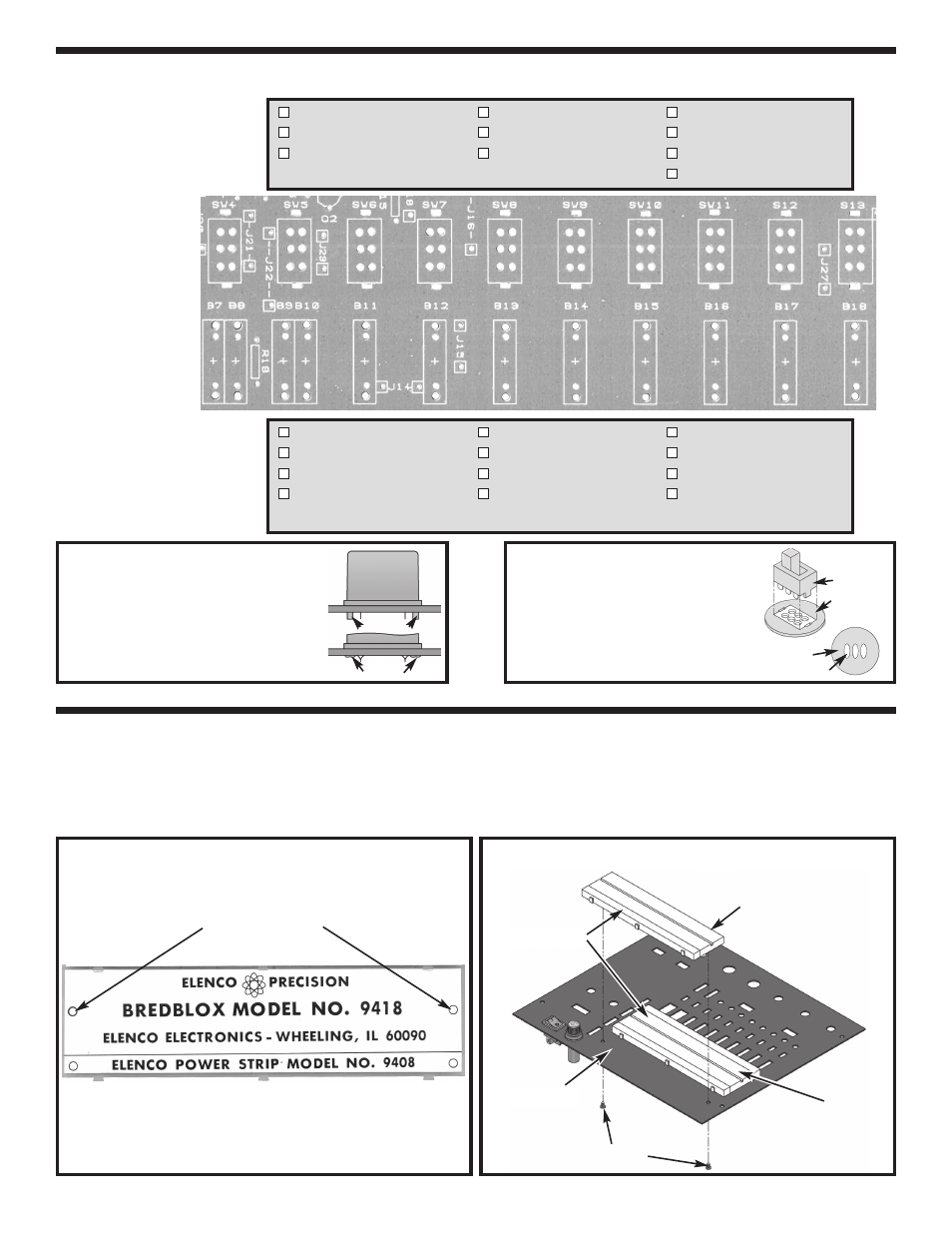
Figure F
Mount the switch onto the legend side
of the PC board as shown. Flip the
board over and solder the part into
place. Be sure to keep the three
soldered sets of leads separate as
shown.
INSTALL COMPONENTS TO PC BOARD
INSTALL COMPONENTS TO FRONT PANEL
r
Interlock the breadboard to the bottom edge of the existing breadboard on the top panel as shown in Figure H.
Fasten the breadboards in place with two #4 x 1/4” AB black screws from the back side of the panel. Use the
holes on the 9426 breadboard as shown in Figure G. CAUTION: Do not remove the paper backing from the
breadboard.
Use these holes
Figure G
Figure H
-42-
SW4 - Slide switch
SW7 - Slide switch
SW10 - Slide switch
SW5 - Slide switch
SW8 - Slide switch
SW11 - Slide switch
SW6 - Slide switch
SW9 - Slide switch
SW12 - Slide switch
(see Figure F)
SW13 - Slide switch
Start Here
B7 - 4-pin Bredblox
B11 - 4-pin Bredblox
B15 - 4-pin Bredblox
B8 - 4-pin Bredblox
B12 - 4-pin Bredblox
B16 - 4-pin Bredblox
B9 - 4-pin Bredblox
B13 - 4-pin Bredblox
B17 - 4-pin Bredblox
B10 - 4-pin Bredblox
B14 - 4-pin Bredblox
B18 - 4-pin Bredblox
(see Figure E)
Continue
Figure E
Hold the bredblox down flush to the PC
board from the top legend side and
solder the metal pins into place. Then,
melt the plastic pins with your soldering
iron to hold the plastic blocks in place as
shown.
Note: The 9418 and the power strip 9408 make
up the 9426 breadboard.
Switch
Legend side
of PC board
Foil side of
PC board
Solder
9830
9426
Top panel
Breadboards
#4 x 1/4” Screws
Plastic Pins
Melt Pins